

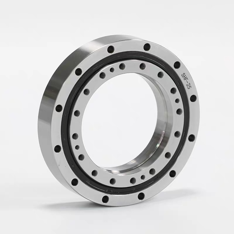
SHF / SHG cross roller bearings provide output support for compatible harmonic reducer mechanisms, including assemblies needing a central service passage. Compare reference sizes, read the section drawing and define the interface review. Start with the complete reducer configuration and available passage, then assess mounting, loading and accuracy requirements.
The SHF / SHG product directory groups the available family references. A bearing’s central opening is only one part of a hollow-shaft system: surrounding flanges, shafts, seals and internal parts also determine the usable passage. Plan the complete service route before choosing a candidate.
Harmonic Drive identifies SHF-2UH and SHG-2UH as hollow-shaft gear units with cross roller output support and a flange for attaching the load. SHG is the high-torque gear-unit alternative. Standard and lightweight configurations require their own interface checks; a gearbox designation does not specify every replacement bearing detail. [1, 2]
The flange support bearing reacts loads from the driven equipment. The wave-generator flexible bearing is a separate component in the strain-wave transmission. Confirm the component’s location when requesting a replacement. For another output-support layout, compare the CSG / CSF selection page using the actual drawings.
The series illustration shows the central opening, section details and mounting circles. d and D identify the bore and outside diameter; H, C, B and B1 locate axial dimensions. dm and dn mark mounting pitch circles, while d1, d2 and d3 identify additional diameter references. Values must be taken from the corresponding model drawing rather than estimated from image proportions.
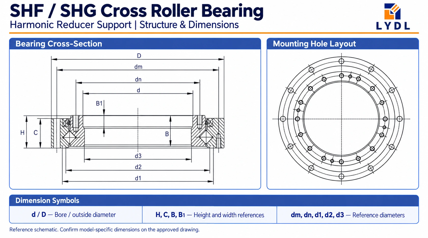
In particular, d and d3 locate different features. Check their mating components and axial positions before assigning either value to a cable or shaft clearance. The plan view illustrates a mounting pattern; it does not prescribe the illustrated hole count for every size. Inner pitch-circle data and hole specifications need a separate drawing check.
The tables below retain the existing LYDL reference dimensions in millimetres and separate the main envelope from secondary interfaces. Published entries cover sizes 14–50. A size reference is not the bore diameter: for example, SHF/SHG-25 has a listed d value of 67 mm. Confirm additional sizes through a drawing review.
| Model reference | d | D | H | C | B | B1 | Drawing |
|---|---|---|---|---|---|---|---|
| SHF/SHG-14 | 38 | 70 | 15.2 | 14.2 | 13.7 | 5 | Drawing |
| SHF/SHG-17 | 47 | 80 | 17 | 16 | 16.4 | 6.5 | Drawing |
| SHF/SHG-20 | 54 | 90 | 18.5 | 17.5 | 17.5 | 7 | Drawing |
| SHF/SHG-25 | 67 | 110 | 20.7 | 18.7 | 19.7 | 7.5 | Drawing |
| SHF/SHG-32 | 88 | 142 | 24.4 | 23.4 | 23.4 | 8 | Drawing |
| SHF/SHG-40 | 108 | 170 | 30 | 29 | 28.5 | 9.5 | Drawing |
| SHF/SHG-50 | 135 | 214 | 36 | 34 | 34.5 | 11 | Drawing |
| Model reference | d3 | d1 | d2 | dm | Drawing |
|---|---|---|---|---|---|
| SHF/SHG-14 | 36 | 57 | 53 | 64 | Drawing |
| SHF/SHG-17 | 44.2 | 68.1 | 64 | 74 | Drawing |
| SHF/SHG-20 | 51.3 | 78 | 72.6 | 84 | Drawing |
| SHF/SHG-25 | 64.2 | 94.8 | 90 | 102 | Drawing |
| SHF/SHG-32 | 84 | 123 | 117.6 | 132 | Drawing |
| SHF/SHG-40 | 106 | 148 | 142.6 | 158 | Drawing |
| SHF/SHG-50 | 129 | 188 | 182.6 | 200 | Drawing |
For size 20, the reference envelope includes d = 54 mm, D = 90 mm and H = 18.5 mm; d3 is 51.3 mm. These dimensions help screen candidates. The ring interfaces, thread details, hole depths, seals and tolerances still require verification against the intended assembly.
List what passes through the axis: electrical cables, pneumatic lines, a shaft, optical components or a rotary union. Include connector dimensions and assembly access; installation may need more space than the cable occupies in service.
Review clearance throughout the planned travel, allowing for relative movement, bends and adjacent parts. Define how hoses and cables are restrained and whether their motion requires a separate routing device. The bearing supports the mechanical output; it does not itself solve service twisting or establish the full gearbox’s through-bore capacity.
Use two interface checks: one for the stationary support and another for the driven flange. Compare locating diameters, shoulder contact, axial offsets and the complete fastening pattern. Record mounting pitch circles, hole quantity, thread size, engagement depth and any countersinks or spotfaces.
Keep those details together on one controlled drawing revision. A nominally similar flange can have incompatible registers or bolt access. Confirm that installed fasteners clear internal moving parts and that the supporting faces are flat and clean. Apply the specified tightening sequence and torque, then inspect running behaviour after clamping.
Describe the loading at the bearing location, rather than supplying payload mass alone. Include force direction, centre-of-gravity position, tooling offsets, acceleration, stopping events and any process force. An overhung load can create a significant overturning moment even when its mass appears modest.
For an illustrative single-force case, 200 N acting perpendicularly at a 0.15 m lever arm produces 30 Nm. This is a geometry example, not a permissible load for a listed model. Review radial and axial loading, moment capacity, required life and the assembly’s stiffness together. Variable cycles also need the time spent at each loading and output-speed condition.
The current LYDL dimensional table does not provide confirmed SHF / SHG bearing ratings. Request C, C0 and applicable moment data for the supplied configuration. C denotes basic dynamic load rating; C0 denotes basic static load rating. Original gear-unit torque, output-bearing specifications and complete-unit mass remain reference data for their stated assembly and cannot be assigned directly to a LYDL component.
Describe the required rotation at the driven flange: radial runout, axial runout, allowable tilt and running torque. Specify where measurements are taken and whether acceptance is before or after mounting. Clearance or preload must be assessed alongside supporting stiffness; a catalogue accuracy label alone does not define the finished mechanism’s performance.
Identify temperature, contamination, lubrication access and sealing needs. For short reversing movements, discuss the motion profile and lubrication requirements explicitly. Semiconductor and medical equipment may impose additional material, cleanliness or qualification conditions. Compare alternative constructions in the LYDL cross roller bearing catalogue.
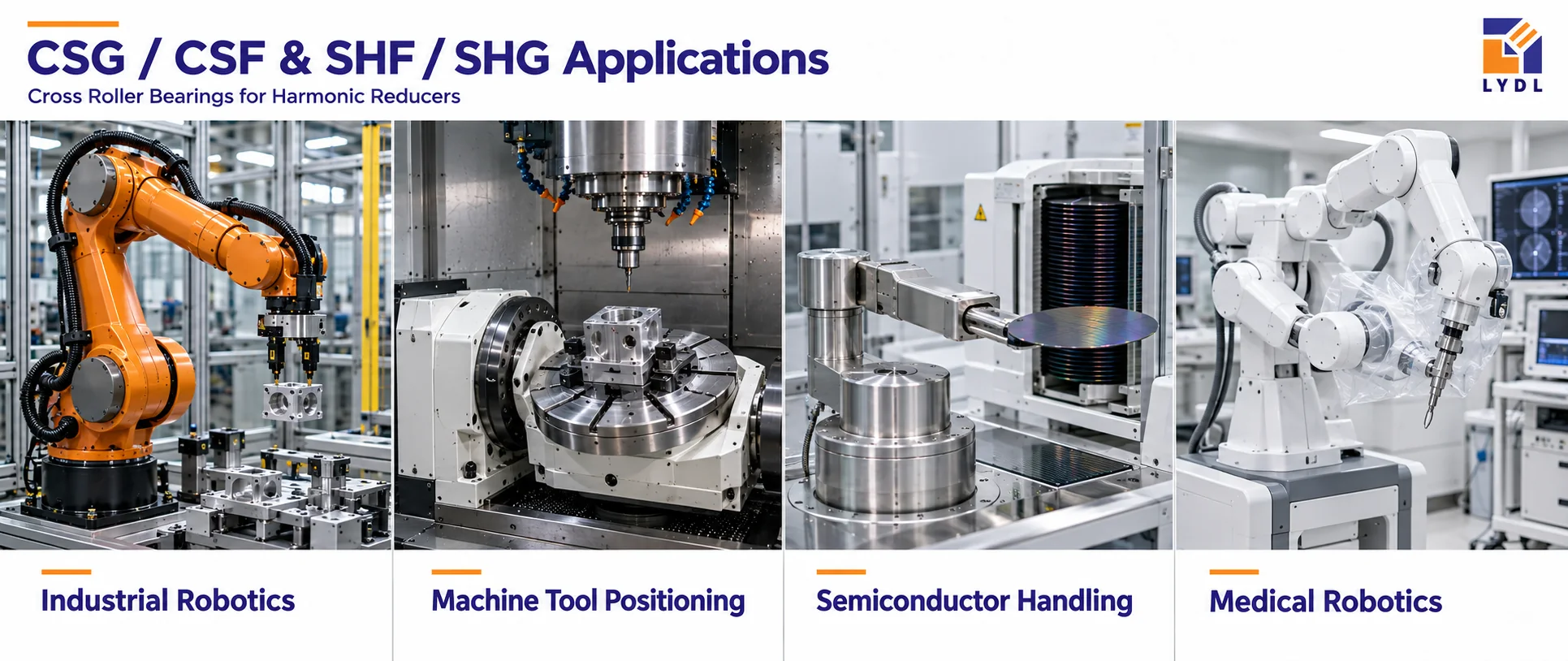
These representative applications explain the mechanical role of output support. They do not confirm fit in a particular machine or establish regulatory suitability. Harmonic Drive’s application examples cover the wider equipment fields. [3]
Define acceptance characteristics before placing the order. For this family, bore steps, seating faces and hole interfaces should be checked alongside specified runout and running characteristics. Request records tied to the part identification and approved drawing. LYDL’s manufacturing information explains the available inspection approach.
Agree anti-corrosion protection, individual wrapping, ring restraint and outer packing for the transport route. Keep machined surfaces protected until installation, and follow the supplied handling instructions when removing protective materials.

It is a bearing reference dimension in this drawing. The assembled passage can be restricted by shafts, flanges, seals or internal components. Check the full axis section and connector access before confirming routing space.
They describe different diameters at the indicated section features. Determine which component mates with each surface and where it sits axially. Treating them as interchangeable dimensions can lead to a clearance or locating error.
The published LYDL entries cover sizes 14–50. Send the complete size-65 requirement and drawing for availability and interface review; dimensions from another unit configuration should not be used to fill the missing row.
SHG identifies a high-torque gear-unit family. Compare the actual output-bearing specification and mounting arrangement to establish support capacity. The gearbox family label alone does not certify a replacement bearing’s load rating.
Review the union’s envelope, supports, mounting access and service connections throughout travel. Include any forces transferred to the bearing and verify clearance against the complete assembly drawing, not only the nominal bore.
Request an SHF / SHG drawing review from LYDL. Provide the reducer identification, required quantity, assembly section, mounting dimensions and working load profile. Include your passage requirement, accuracy targets, inspection records and delivery destination. Clear interface information helps establish an appropriate component specification before quotation and production.
LYDL is the supplier of its own bearing products. Referenced brand and series names identify comparison families. Confirm supplied dimensions, performance and inspection criteria in the agreed LYDL drawing and order specification.