

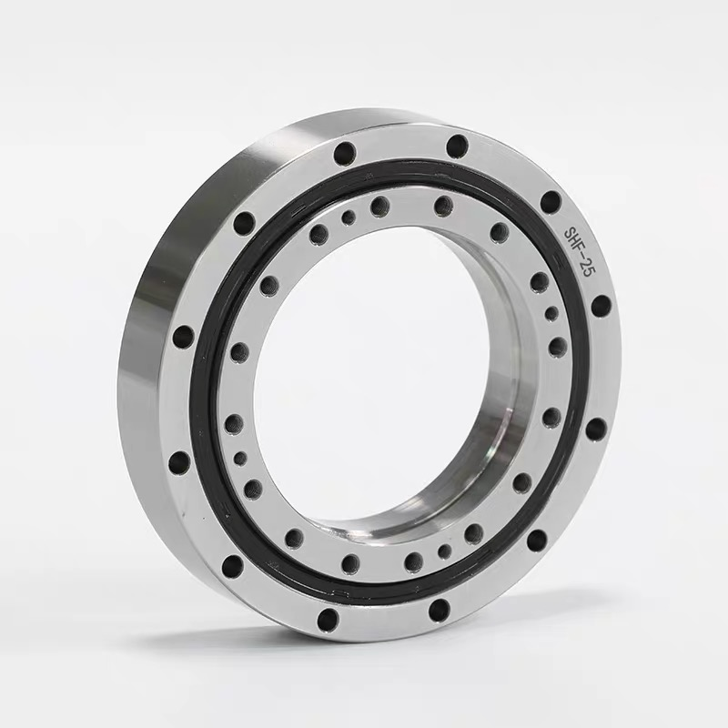
SHF-50 / SHG-50 cross roller bearing reference dimensions are 135 mm bore, 214 mm outside diameter and 36 mm overall height. The separate d3 entry is 129 mm. A large central service or equipment envelope should be checked with the output flange, surrounding supports and handling arrangement. This size-50 page focuses on integrating those features without mistaking passage space for a load-capacity specification.
Compare this model with the SHF / SHG selection guide before confirming the interface.
Provide an assembly section through the bearing, housing and the device occupying the centre. Identify stationary and moving parts, their supports and the direction of installation. Include fittings, connectors, guards and required maintenance access. The largest visible opening is not necessarily the limiting section of the assembled passage.
If the central device has its own support or reaction loads, show where those forces enter the mechanism. Avoid using the bearing bore as an assumed locating or carrying surface without a confirmed design. The review should distinguish clearance, centring and mechanical support. That information is more useful than describing the device only by a nominal outside diameter.
Show whether the central device can be installed and removed independently of the output support. Include protective covers and service fittings in this review. A mechanism may have adequate running clearance yet require a different assembly sequence, so clarify both operating and maintenance envelopes before machining the surrounding parts.
The reference section identifies d = 135 mm and d3 = 129 mm at different features. D = 214 mm defines the outside diameter. H = 36 mm is the overall axial reference, with C = 34 mm, B = 34.5 mm and B1 = 11 mm assigned to further axial details. Check their positions in the flange stack-up, especially where equipment is attached close to the bearing.
d1 = 188 mm and d2 = 182.6 mm identify secondary diameters; dm = 200 mm is the published outer mounting circle. Hole count, threads and engagement depths remain drawing-specific. Use the SHF / SHG bearing category to locate family references, then obtain the full size-50 interface drawing instead of deriving unspecified mounting details from the generic illustration.
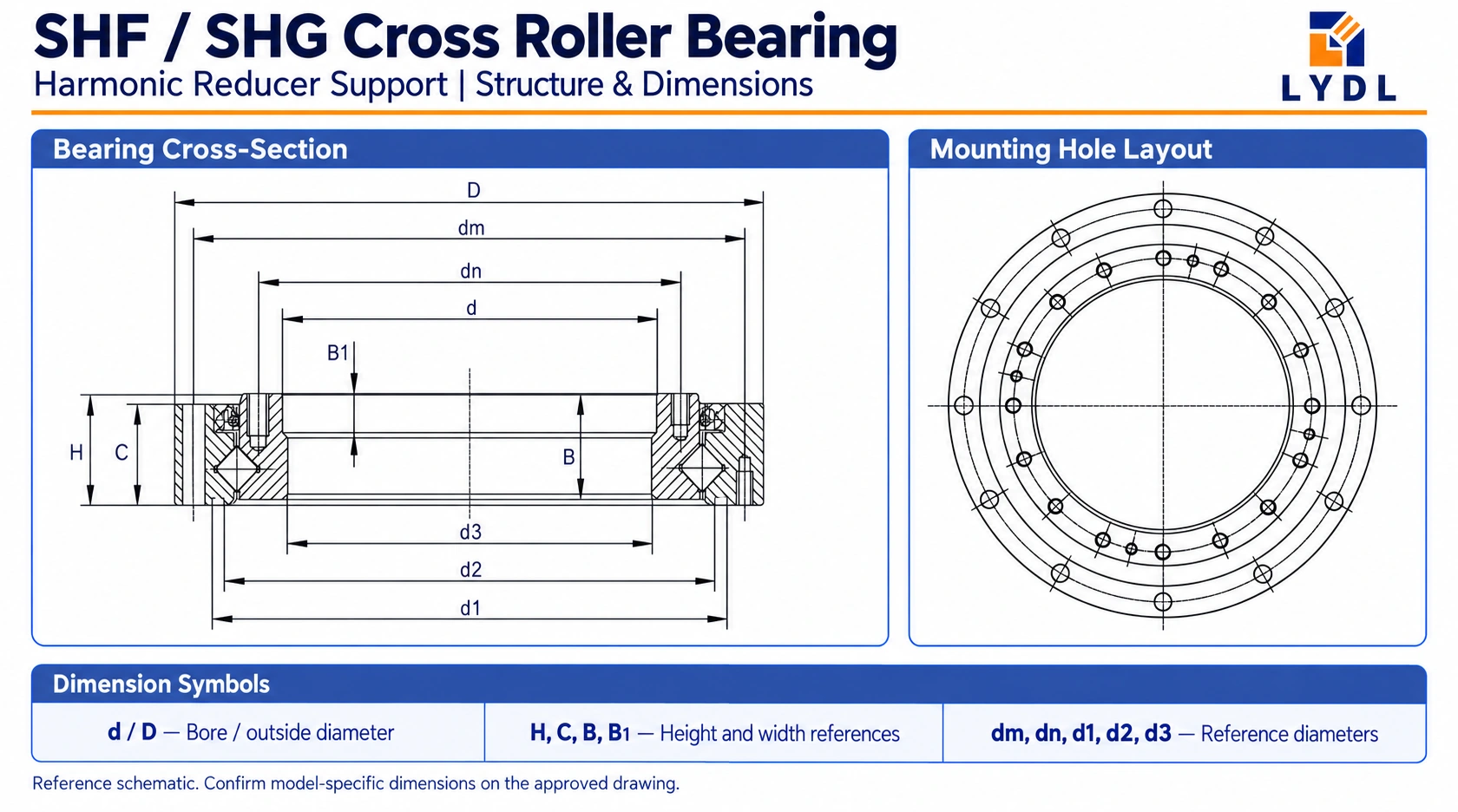
| Reference feature | Value |
|---|---|
| d (mm) | 135 |
| d3 (mm) | 129 |
| D (mm) | 214 |
| H (mm) | 36 |
| C (mm) | 34 |
| B (mm) | 34.5 |
| B1 (mm) | 11 |
| d1 (mm) | 188 |
| d2 (mm) | 182.6 |
| dm (mm) | 200 |
Dimensions: existing LYDL selection reference. The approved model drawing defines tolerances, variant mapping and supplied interfaces.
A hollow flange and its surrounding housing must provide the support required by the driven load. Identify intended contact faces, centring registers and bolted connections. Review the adapter or equipment mount with the designer rather than assuming that a larger bore or outside diameter guarantees an adequately stiff assembly.
Check access for the specified hardware with the central device installed. Confirm that the device's support does not obstruct fastening, impose an unintended force or prevent full seating. If the design introduces a new adapter, include its axial offset and load path in the review. Changes to the surrounding structure can matter even when the bearing reference itself is unchanged.
Describe the output load with directions, lever arms and motion history. Include the supported equipment, attachments, process forces and any central-system reactions carried by the flange. State the demanding orientations and stopping conditions required by the design. A passage large enough for the device does not determine bearing life or permissible overturning moment.
The original SHF and SHG unit information supplies comparison context for hollow-shaft output support. Confirm dynamic, static and moment data for the actual LYDL bearing configuration before a capacity assessment. Keep gear transmission torque and complete-unit mass separate from component support data and handling mass. The LYDL cross roller bearing range supports comparison where the machine requires a different mechanical arrangement.
Confirm the supplied component's mass and handling instructions before assembly. Provide suitable temporary support and protect locating faces while aligning the bearing and equipment. Do not assume a mounting feature is an approved lifting point. Keep handling fixtures and final fastening requirements clearly distinguished in the installation plan.
Define runout and loaded flange behaviour at the relevant working radius, with mounting and load conditions stated. Agree clearance or preload, seals, lubricant and running checks for the supplied component. After fastening, inspect the intended movement and central-device clearance. The completed drive's positioning accuracy does not replace the bearing's own dimensional and rotational acceptance criteria.
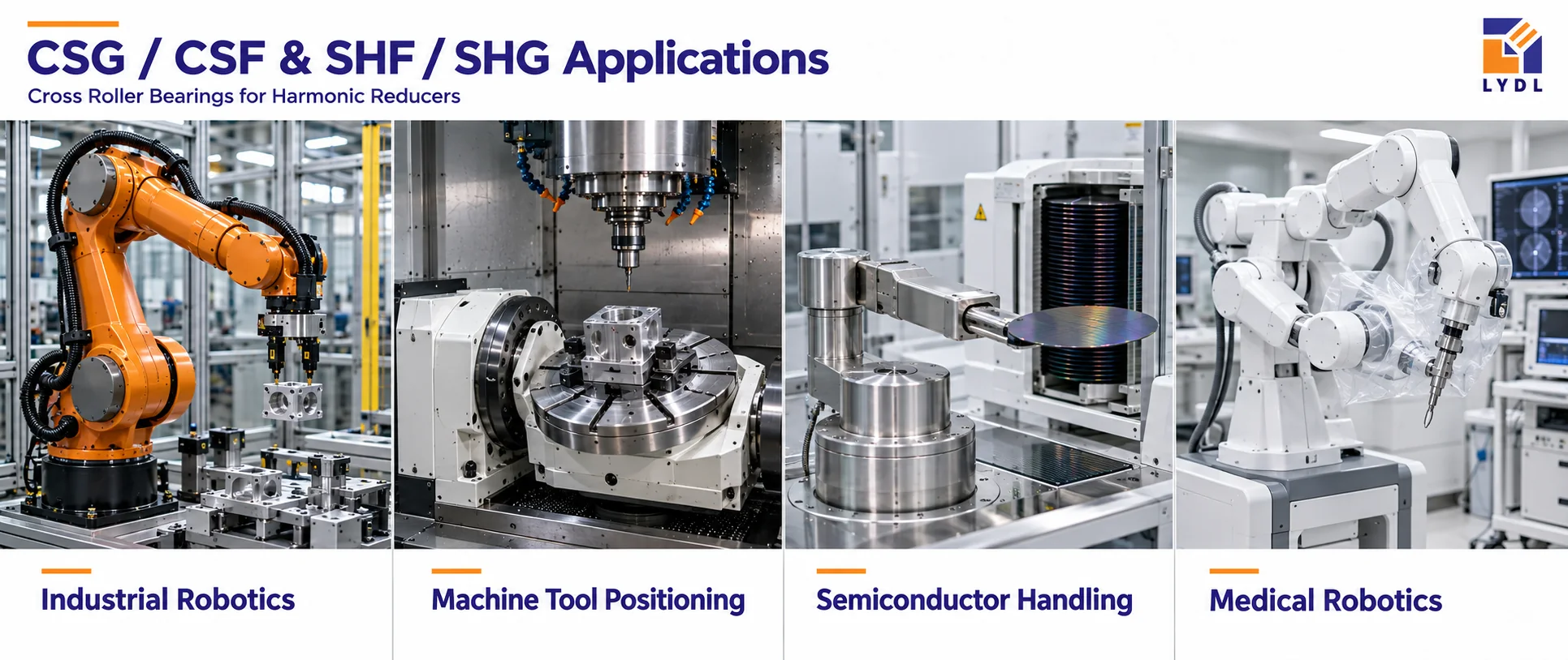
Industrial robotics can involve a routed joint or process support around central equipment. Machine-tool positioning may use a hollow orienting mechanism with a fixture or service device, provided its process forces are defined. Semiconductor handling can involve a larger transfer assembly with separate environmental requirements. Medical positioning equipment may employ comparable support concepts with independent application validation.
The graphic illustrates sectors and mechanical roles. It does not demonstrate an approved size-50 installation or establish permissible payload, cleanliness or device suitability. Review the exact central envelope, mounting interfaces and supplied performance for the actual mechanism.
Identify the bore steps, seating diameters, flange dimensions and model-specific fixing details in the inspection plan. State the rotational measurements and conditions, then request records tied to the approved part and revision. If acceptance includes the attached equipment, define that assembly test separately from bearing inspection. Consult LYDL company and manufacturing information for supplier background.
Discuss protected faces, individual restraint and transport packaging appropriate to the actual component. Confirm how the package will be supported and opened, particularly when stored as a spare. Use inspection and packing imagery that matches real activities, with representative arrangements labelled honestly. The image cannot establish an unconfirmed component mass, capacity or additional quality test.

It is one reference feature in the bearing section. Check the assembled route, steps, fittings and installation approach. Include maintenance clearance and supports before confirming that the central equipment can be integrated.
Passage space and bearing capacity are different requirements. Assess the actual forces, moments, motion and supplied component ratings, together with housing stiffness. A larger opening alone does not establish permissible payload or life.
Only if the approved design establishes that locating and support function. Identify intended contact surfaces and how forces are carried. A nominally fitting diameter should not be treated as an authorised seat without a controlled interface specification.
Confirm mass for the actual supplied bearing and configuration. Complete reducer mass or an unverified earlier table entry may refer to another item. Use the confirmed information and approved handling method when planning fixtures and installation.
Define the assembly-level test, load, measurement points and conditions separately from component inspection. Keep the bearing's dimensional and rotational records identifiable. A loose-bearing report cannot certify the behaviour of an unspecified complete equipment assembly.
Send the size-50 assembly section, central-device supports and output-load cases through LYDL technical enquiry. Include handling needs, quantity and the requested inspection scope. LYDL can review the component drawing and supply configuration with the integration requirements clearly separated and documented.
LYDL supplies its own bearings. Referenced brand names identify comparison families; agreed drawings and order specifications define supplied performance.