

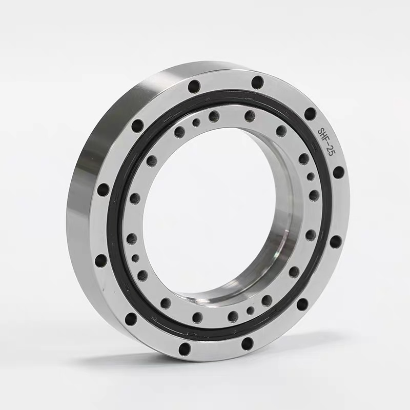
SHF-20 / SHG-20 cross roller bearing selection uses LYDL reference dimensions of 54 mm bore, 90 mm outside diameter and 18.5 mm overall height. A separate d3 feature is listed at 51.3 mm. For a transfer mechanism carrying vacuum or sensor services, this guide brings the passage, motion cycle and environmental requirements into one drawing review without assuming a cleanroom qualification.
Compare this model with the SHF / SHG selection guide before confirming the interface.
A transfer head may route vacuum, electrical feedback and pneumatic services through the same axis. Identify each line, connector and restraint, then show its path through the complete assembly. The bearing bore is one reference in that route; internal shafts, covers and sealing arrangements can reduce the opening available to services. Check the narrowest section and installation access.
State whether the services move with the head or connect through a separate routing device. The output bearing does not provide a vacuum seal or prevent service twisting merely because it has a central opening. Specify the relevant connectors and allowable movement with the system designer. This avoids treating a bearing dimension as a complete solution for the transfer head's service requirements.
Identify where each vacuum connection is fixed and where it moves. Keep its routing and system sealing requirements separate from the bearing mounting dimensions so the interface review does not imply an unverified service function.
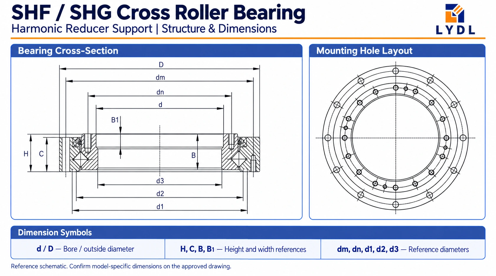
In the LYDL reference, d = 54 mm and d3 = 51.3 mm belong to different section features. D = 90 mm defines the outside envelope. H = 18.5 mm, C = 17.5 mm, B = 17.5 mm and B1 = 7 mm identify axial details; equal B and C values do not imply that the labels locate the same surface.
d1 = 78 mm and d2 = 72.6 mm identify further diameters, while dm = 84 mm is the outer mounting-circle reference. Use the model-specific drawing for the hole pattern, threads and depths absent from the numerical table. The SHF / SHG bearing category provides related family references, but those interfaces should not be combined with size-20 dimensions to fill an unspecified feature.
| Reference feature | Value |
|---|---|
| d (mm) | 54 |
| d3 (mm) | 51.3 |
| D (mm) | 90 |
| H (mm) | 18.5 |
| C (mm) | 17.5 |
| B (mm) | 17.5 |
| B1 (mm) | 7 |
| d1 (mm) | 78 |
| d2 (mm) | 72.6 |
| dm (mm) | 84 |
Dimensions: existing LYDL selection reference. The approved model drawing defines tolerances, variant mapping and supplied interfaces.
The support sees different conditions while approaching a part, carrying it and releasing it. Include the head, payload and service forces at the relevant offsets. Provide acceleration, output motion and the time spent in each stage. Identify any contact force or stopping event required in the machine assessment. Vacuum holding capacity is a separate system topic from bearing support capacity.
For a revised cycle, state what has changed: workpiece, tool reach, acceleration or movement pattern. A previously acceptable mechanism should not be assumed suitable for every new task. Confirm the component's radial, axial and moment data for the agreed configuration. No LYDL load figures are supplied here where they have not been verified for the standalone bearing.
If the mechanism operates in a controlled environment, explain the cleanliness, material and lubricant restrictions that apply. Identify whether the bearing is enclosed and what particles or process substances may reach it. A semiconductor application illustration is not evidence of a cleanroom class or compatibility with every vacuum process. Any special requirement needs confirmation in the supplied specification.
Separate environmental qualification from dimensional interchangeability. A bearing that matches the flange may still need review of sealing, lubrication and maintenance access. Provide the operating temperature and motion profile relevant to those decisions. Use the LYDL cross roller bearing range to compare constructions if the equipment design calls for another support arrangement, while retaining the specific process requirements.
Specify the required runout or flange movement at the transfer tool and identify the measurement load. State whether acceptance is performed on the loose component or assembled head. Running resistance may include service bends, seals and adjacent parts, so test conditions should identify the installed configuration. A general accuracy statement for the reducer cannot replace these component and assembly checks.
Prepare the mating seats and verify the locating surfaces before fastening. Inspect the movement across the planned travel with the services fitted and secured. Look for interference at covers, clamps and connectors. If motion changes after mounting, check contact faces and the service route before assuming a bearing tolerance issue or changing the order specification.
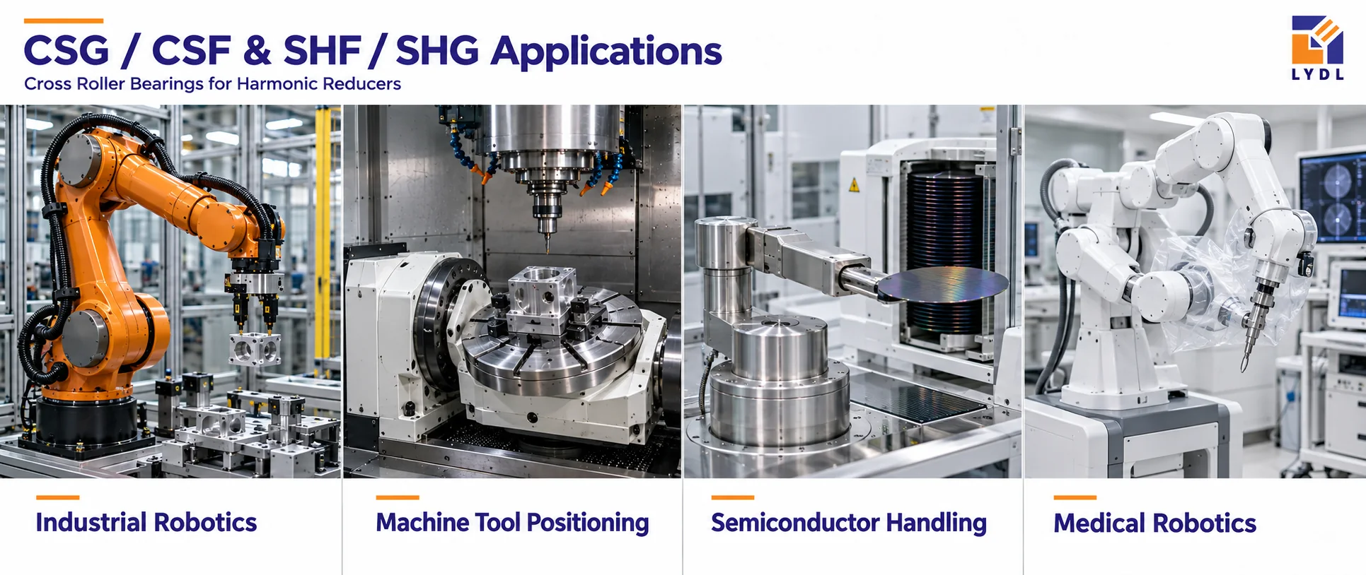
Industrial robotics may use this output support in a serviced end-effector joint. Machine-tool positioning can involve a rotary attachment with sensor or fluid connections, provided process loads are defined. Semiconductor handling is a relevant context for articulated transfer heads, with cleanliness assessed independently. Medical robotics can involve a positioning joint whose service route and device requirements need separate validation.
The shared image is illustrative. It does not show a qualified installation of this model or establish contamination limits. Identify the mechanical location, services and environmental acceptance for the particular equipment being designed or maintained.
Agree the critical bore steps, flange seats, mounting details and rotational checks on the approved drawing. If special cleanliness or lubrication documentation is required, describe it explicitly and confirm availability. A standard dimension report should not be presented as evidence of an additional process qualification. See LYDL company and manufacturing information for company context during the supplier review.
Discuss how protection is retained during shipment and removed at installation. Keep mating surfaces separated from loose accessories and specify packing suitable for the planned storage and transport. Use the inspection and packaging image only for activities and arrangements it actually depicts; a representative graphic does not establish unconfirmed model-specific tests.

The central route and bearing support are separate from the system's vacuum sealing. Specify the complete service and sealing design. Matching a passage diameter does not establish leak performance, vacuum compatibility or a rotary connection function.
They reference different locations in the section even when their numerical values coincide. Read each symbol at its drawn feature and check the mating stack-up. Do not collapse the two labels into an assumed single surface.
Include pickup, travel, release and relevant stopping events. State tool and payload geometry, offsets, force directions and acceleration. Separate vacuum holding requirements from the mechanical forces transmitted to the bearing support.
No cleanroom class is assigned without supporting qualification for the supplied configuration. Describe lubricant, sealing, material and contamination requirements in the enquiry. Environmental suitability must be confirmed for the actual machine and operating conditions.
Identify required cleanliness, lubricant or material records during the technical review and confirm what can be supplied. They are additional to ordinary dimensional inspection. Record the agreed documentation and acceptance scope in the order.
Send the size-20 transfer-head section, service route and process requirements via LYDL technical enquiry. Include the complete unit identification, motion stages and quantity. LYDL can review the bearing interfaces and confirm the applicable inspection and supply scope before quotation.
LYDL supplies its own bearings. Referenced brand names identify comparison families; agreed drawings and order specifications define supplied performance.