

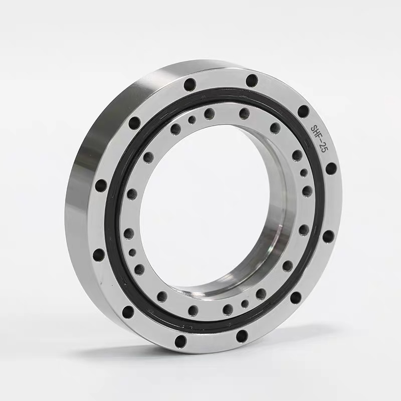
SHF-40 / SHG-40 cross roller bearing references list a 108 mm bore, 170 mm outside diameter and 30 mm overall height, with d3 = 106 mm at a separate feature. A hollow axis may provide generous service space yet still be difficult to maintain. This size-40 guide concentrates on removal access, controlled replacement interfaces and checks after reassembly.
Compare this model with the SHF / SHG selection guide before confirming the interface.
Plan maintenance with the services, covers and driven equipment in place. Identify what must be disconnected or supported before the output bearing is released. A large central opening does not guarantee access to every fastener or enough space to withdraw the component. Show the removal direction, tools and temporary support arrangement in the service plan.
For an existing machine, record the routing and flange orientation before dismantling. Mark which connections locate the bearing and which secure other equipment. Preserve the exact reducer identification and any special revision. The replacement enquiry should describe the intended retained interfaces, not merely the outside dimensions of the removed part.
Before removing the existing support, identify how the driven equipment will be held and which services must be released. Record the order of these operations, necessary supports and access clearances in the maintenance plan. Temporary support and access are assembly-design requirements, not handling instructions that can be inferred from the bearing diameter.
The reference lists d = 108 mm and d3 = 106 mm at distinct section locations. Their small numerical difference is not a clearance allowance to apply arbitrarily; determine the mating feature and its axial position. D = 170 mm is the outer envelope, and H = 30 mm is the overall axial reference.
C = 29 mm, B = 28.5 mm and B1 = 9.5 mm locate further axial details. d1 = 148 mm, d2 = 142.6 mm and dm = 158 mm identify additional diameter and mounting references. Compare them with the housing and driven flange on the complete drawing. The SHF / SHG bearing category provides a family overview, while the model specification must supply the missing fixing-hole quantities, threads and depths.
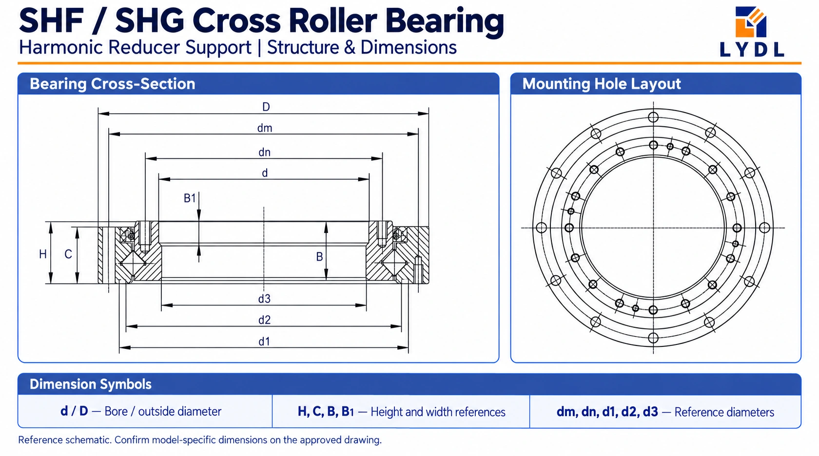
| Reference feature | Value |
|---|---|
| d (mm) | 108 |
| d3 (mm) | 106 |
| D (mm) | 170 |
| H (mm) | 30 |
| C (mm) | 29 |
| B (mm) | 28.5 |
| B1 (mm) | 9.5 |
| d1 (mm) | 148 |
| d2 (mm) | 142.6 |
| dm (mm) | 158 |
Dimensions: existing LYDL selection reference. The approved model drawing defines tolerances, variant mapping and supplied interfaces.
A service bracket, conduit or connector can obstruct the output flange without being part of the bearing's locating arrangement. Identify each attachment and verify removal access. Confirm that screws used for surrounding hardware do not interfere with the bearing fasteners or rotating parts. If an access change is needed, document the redesigned component and its effect on the interface.
Do not rely on the old assembly's appearance to establish a correct register or axial position. Inspect mating surfaces for damage, repair history or raised edges. Determine whether the original seating and hardware are being retained. A well-defined replacement drawing is preferable to selecting a nominally similar part and discovering incompatible contact faces during reassembly.
Maintenance provides an opportunity to record the present load and motion. Include any changed tool, fixture, payload location or process force. Describe output movement and demanding stopping or holding conditions. Services routed through the centre may also apply forces at their restraints; identify whether those forces enter the driven equipment.
Obtain the supplied bearing's confirmed load and moment data. Original SHF/SHG gear-unit specifications describe their stated assemblies and should not be assigned to an unidentified replacement component. A changed operating task can require a fresh assessment even when the same size is retained. Use the LYDL cross roller bearing range when reviewing a different construction and establish its housing implications before ordering.
Set the measurement locations, mounting state and test load for runout or flange-movement checks. Agree clearance or preload, running behaviour and the supplied sealing and lubrication arrangement. Keep complete-drive positioning accuracy distinct from mechanical acceptance of the support bearing. Record the conditions so maintenance staff can reproduce the checks after another replacement.
Clean and inspect the intended contact faces before clamping. Follow the approved fastening procedure and check rotation with covers and services restored. Look for rubbing, restricted travel and changes caused by nearby brackets. If the installed result differs from the loose-component observation, examine the seating and attached hardware rather than silently changing the bearing acceptance criteria.
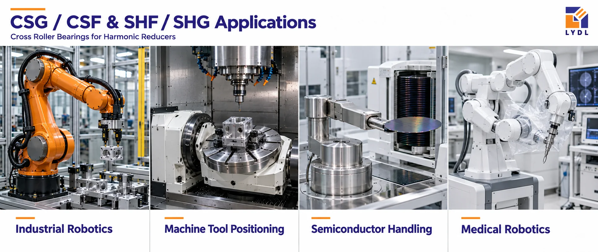
Industrial robotics may require service access to a routed joint carrying changing tools. Machine-tool positioning may use a hollow orienting axis with internal connections and measured flange behaviour. Semiconductor equipment can involve articulated transfer mechanisms whose maintenance procedure also protects the controlled environment. Medical positioning systems may need documented reassembly and independent device validation.
The image presents representative equipment fields. It does not certify a maintenance procedure or show confirmed installations of this exact model. Use the actual drawings and operating requirements when establishing access, support capacity and acceptance checks.
Specify the critical seats, bore steps, mounting interfaces and rotational checks in the inspection scope. Ask for part identification and the drawing revision on the report. Retain the removed-part photographs with the approved replacement record, but do not treat wear measurements as intended manufacturing tolerances. The LYDL company and manufacturing information supplies company information for the technical procurement file.
Discuss corrosion precautions and face protection for a stocked spare as well as an immediate installation. Keep packing restraints identifiable so they can be removed according to the supplied instructions. Use truthful inspection and packaging imagery; a generic photograph cannot establish that a particular order received an extra test or special preservation method.

Removal also depends on fastener access, covers, services and the direction of withdrawal. Review the complete assembly and temporary support needs. A large nominal opening does not establish a practical maintenance sequence.
The two values belong to distinct drawn features. Identify their mating parts and axial locations rather than treating their difference as an arbitrary allowance. Use the complete route and controlled tolerances to assess installed clearance.
Document the condition and identify the original intended interface. Wear, damage or earlier repairs may need a separate corrective decision. The approved replacement should match the retained or redesigned interface, not an unexplained worn measurement.
Photograph the route, restraints, connectors and flange orientation. Identify attachments that affect bearing access and note the assembly revision. This information helps restore the reviewed configuration and distinguish service hardware from locating features.
Use the same defined measurement surfaces, mounting conditions, loads and procedure. Retain the approved drawing and report references. Record changes to tooling or routing so a later result is not compared against a different mechanism configuration.
Use LYDL technical enquiry to send the size-40 retained-interface drawing, removal plan and current operating duty. Include the complete unit identification, quantity and required records. LYDL can review the replacement component with access and reassembly acceptance considered together.
LYDL supplies its own bearings. Referenced brand names identify comparison families; agreed drawings and order specifications define supplied performance.