

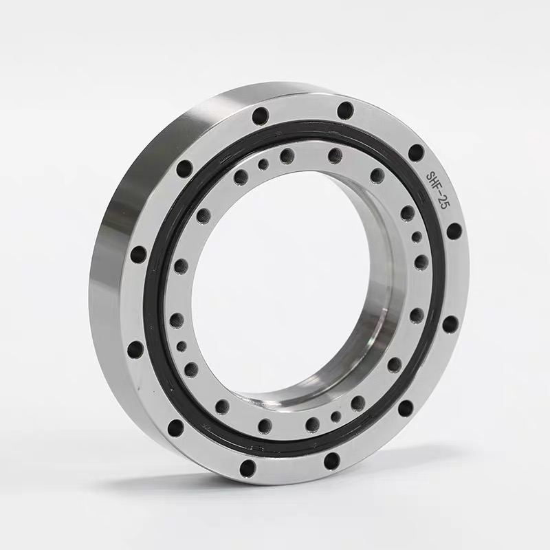
SHF-32 / SHG-32 cross roller bearing references have an 88 mm bore, 142 mm outside diameter and 24.4 mm overall height. The distinct d3 feature is 84 mm. Where a service shaft or central device passes through an articulated axis, check how it is located and supported independently of the output bearing. This size-32 page focuses on coaxial interfaces and the assembled force path.
Compare this model with the SHF / SHG selection guide before confirming the interface.
A shaft passing through the bearing opening may have its own supports, couplings and movement relative to the output flange. Identify those parts on the assembly section. Establish which surfaces locate the shaft and which provide clearance only. The bearing bore should not be assumed to act as a shaft support merely because the shaft fits through it.
Record alignment requirements between the central device, housing and rotating output. Include coupling access and the order of assembly. If the shaft is part of another drive or service system, describe the relative motion and any transferred force. This separates the central system's requirements from the bearing's job of supporting the driven flange.
Include axial movement of the passing shaft and its coupling access in the clearance review. A correct radial opening can still leave interference at an internal shoulder or during installation; show those locations on the complete section.
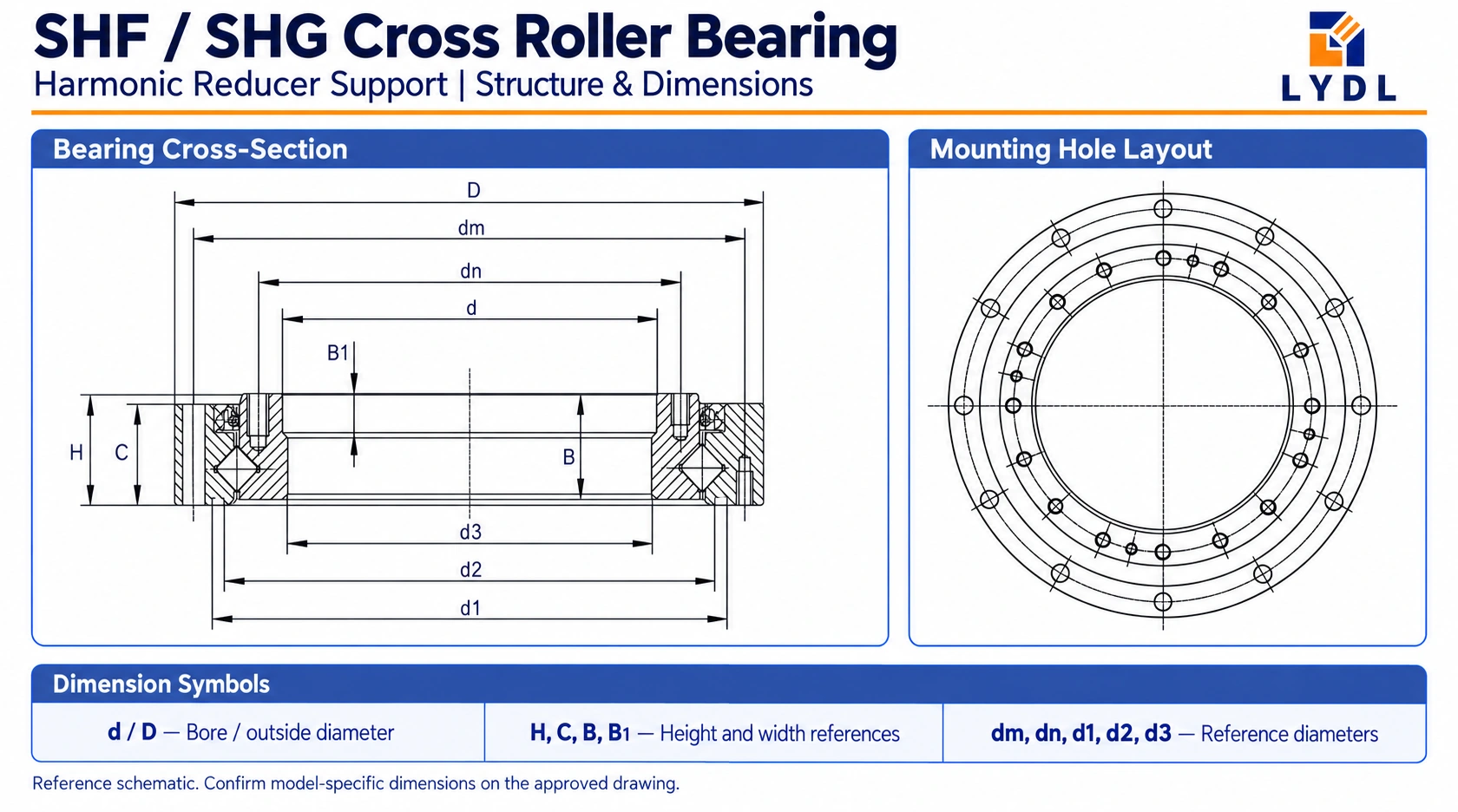
Use d = 88 mm for the labelled bore and d3 = 84 mm for the separate section feature. D = 142 mm is the outer envelope. H = 24.4 mm, C = 23.4 mm, B = 23.4 mm and B1 = 8 mm locate axial details. Although B and C share a value, their drawing locations and mating surfaces remain distinct.
d1 = 123 mm and d2 = 117.6 mm identify additional diameters. The reference dm = 132 mm is the outer mounting pitch circle, not the outside diameter or a guaranteed contact surface. Request the full hole and thread specification on the model drawing. The SHF / SHG bearing category provides size navigation while the section establishes how each reference belongs to the actual assembly.
| Reference feature | Value |
|---|---|
| d (mm) | 88 |
| d3 (mm) | 84 |
| D (mm) | 142 |
| H (mm) | 24.4 |
| C (mm) | 23.4 |
| B (mm) | 23.4 |
| B1 (mm) | 8 |
| d1 (mm) | 123 |
| d2 (mm) | 117.6 |
| dm (mm) | 132 |
Dimensions: existing LYDL selection reference. The approved model drawing defines tolerances, variant mapping and supplied interfaces.
Show the locating registers of the stationary housing, output bearing and central supports together. Identify the required relationship between them and the relevant inspection datums. Nominal diameters alone do not establish coaxiality, face alignment or the installed clearance around the shaft. Specify tolerances and acceptance methods through the controlled drawing review rather than assigning an assumed universal fit.
For a replacement, inspect the mating structure and note any repaired or modified seats. If the shaft rubs or its coupling is misaligned, determine whether the cause is a locating feature, central support or output assembly. Changing the bearing without identifying that relationship can leave the original issue unresolved. Keep observed evidence and dimensional requirements distinct in the enquiry.
The bearing reacts forces from the driven link, tool or fixture. Mark their locations and directions relative to the support, including forces from any attached central-system bracket. State movement, acceleration, reversals and the time spent in loaded positions. The shaft's presence in the bore does not itself determine whether its forces are carried by the output bearing.
Ask for confirmed component dynamic, static and moment data before applying a load calculation. Original SHF/SHG gearbox descriptions and ratings belong to their specified assemblies. Do not import complete-unit torque or mass into the bare bearing specification. Compare the LYDL cross roller bearing range where another support construction is under consideration, and include the resulting changes to the housing interfaces.
Agree which measurements establish bearing acceptance and which establish central-system alignment. For rotational checks, identify the output surface, radius, load and mounted condition. State clearance or preload and running-behaviour requirements for the supplied part. A gearbox accuracy figure cannot define all those component measurements.
Prepare and clean the contact surfaces before fastening. Check rotation after the housing and driven flange are secured, then verify the central-device clearance through its intended movement. Record conditions sufficiently clearly to repeat the test after maintenance. If assembled behaviour changes when the shaft or coupling is installed, investigate the transferred forces and alignment rather than attributing the difference to the bearing by default.
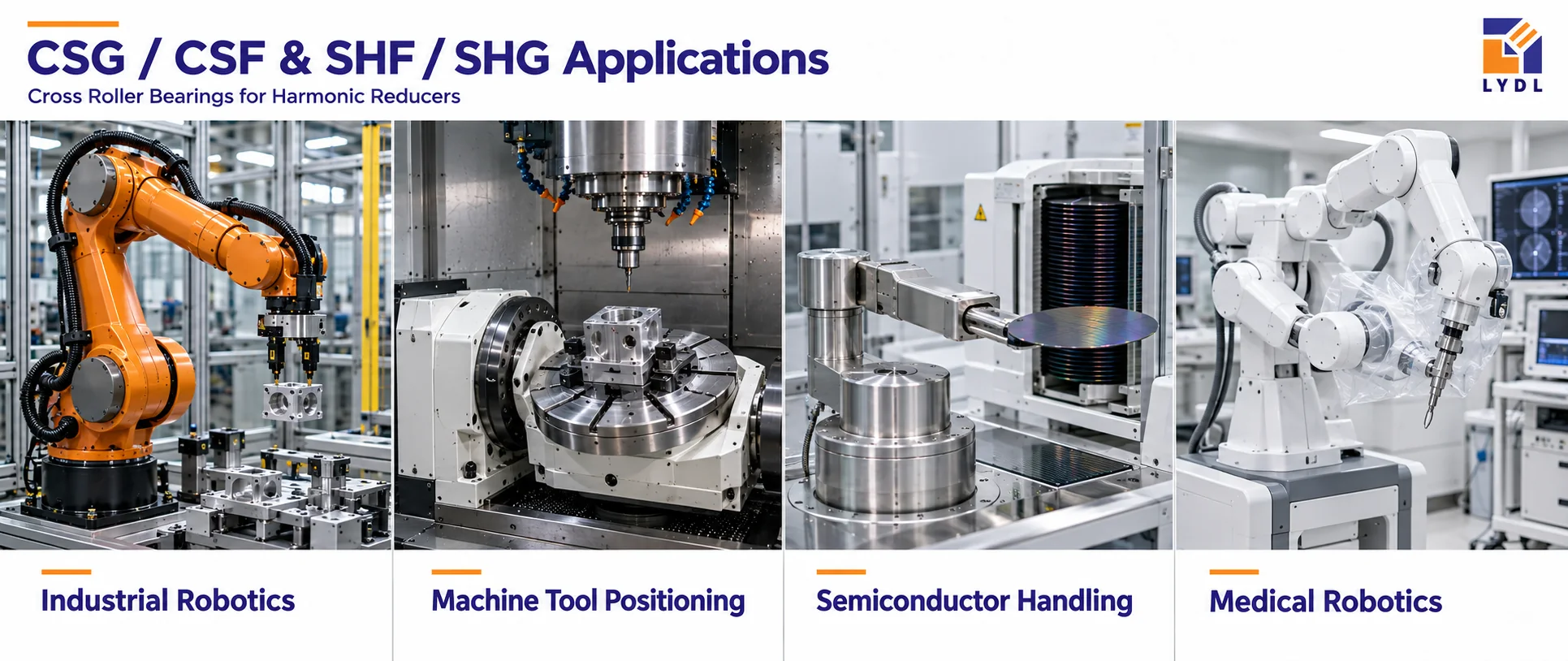
Industrial robotics may use a routed joint with a central shaft, sensor arrangement or service device. Machine-tool positioning can involve an orienting axis whose central system has separate support and alignment needs. Semiconductor handling may combine an articulated transfer axis with vacuum or sensing equipment. Medical robotics may use a positioning mechanism with independently validated internal services.
The shared graphic explains those possible equipment fields. It does not establish exact fit, coaxial tolerances or qualification of this model. The drawing review must address the particular central device and mechanical support arrangement.
The order should identify critical bore steps, locating features, mounting details and rotational checks. If central-device clearance depends on a specific datum relationship, describe it in the assembly documentation and distinguish it from loose-bearing inspection. Record the approved component drawing revision. Consult LYDL company and manufacturing information for supplier information relevant to the procurement review.
Protect the mating faces and central features during shipment, using separation and restraint appropriate to the actual goods. Confirm packing and handling instructions rather than inferring them from an illustration. A neutral inspection image may be shared across families only if it describes the real method and does not claim unverified size-specific tests.

Not automatically. Define the shaft's locating and support arrangement on the assembly drawing. A clearance opening and a shaft-support interface serve different purposes. Identify which components carry the central shaft's forces and relative motion.
It is identified here as the outer mounting pitch circle. Check the actual locating registers separately on the drawing. Treating a bolt-circle dimension as a seat diameter would confuse fastening with centring of the component.
Identify the relevant datums, central supports and output interfaces on the controlled drawing. Agree the tolerances and measurement method for the assembly. Nominal bore and outer diameters alone do not establish a coaxiality requirement or installed result.
Alignment and forces transferred from the central system may affect the assembled behaviour. Record the mounting sequence and test conditions. Check coupling access, support relationships and shaft clearance before attributing a new symptom solely to the output bearing.
Retain the component revision, assembly section, datum relationships and agreed inspection procedure. Identify central supports and clearance features separately. This allows a replacement review to address the same interfaces rather than reconstructing them from a loose bearing.
Send the size-32 assembly section and central-shaft support layout via LYDL technical enquiry. Include the required datum relationships, operating forces and quantity. LYDL can review the bearing drawing with the coaxial interfaces and component acceptance scope explicitly identified.
LYDL supplies its own bearings. Referenced brand names identify comparison families; agreed drawings and order specifications define supplied performance.