

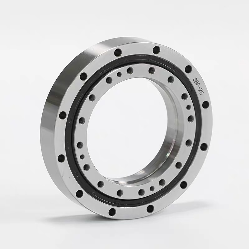
SHF-17 / SHG-17 cross roller bearing references list a 47 mm bore, 80 mm outside diameter and 17 mm overall height, with d3 = 44.2 mm at a separate feature. A routed wrist or sensor-positioning axis needs clearance that remains useful during movement. This size-17 guide concentrates on the service bundle, its restraints and the support conditions at the moving flange.
Compare this model with the SHF / SHG selection guide before confirming the interface.
List the electrical cables, air lines and other services that share the central route. Show their positions and movement rather than representing them only as one nominal diameter. Connectors, protective sleeves and bend requirements may govern the usable space. Identify where the bundle is held on the stationary side and where it attaches to the moving equipment.
Review the travel extremes and any repeated reversal. A route that clears the bore in the neutral position can rub an edge or pull on a connector elsewhere. Define strain relief and service access as part of the mechanism design. The bearing provides mechanical output support, while the bundle restraint and twisting solution require their own design decisions.
Record the bundle position at each inspection point, including the neutral pose and travel extremes. If the harness is replaced, preserve its connector locations and restraint references so a later test does not unknowingly assess a different routing arrangement.
Read d = 47 mm and d3 = 44.2 mm at the separate surfaces shown in the section. D = 80 mm is the outer envelope. H = 17 mm, C = 16 mm, B = 16.4 mm and B1 = 6.5 mm describe additional axial features; B and C should not be substituted for one another simply because they are close in value.
The reference also lists d1 = 68.1 mm, d2 = 64 mm and outer mounting circle dm = 74 mm. Confirm the mating seats and fastening details on the specific drawing. No hole quantities or thread depths should be inferred from the generic plan view. Consult the SHF / SHG bearing category for the family navigation while keeping the size-17 assembly section with the enquiry.
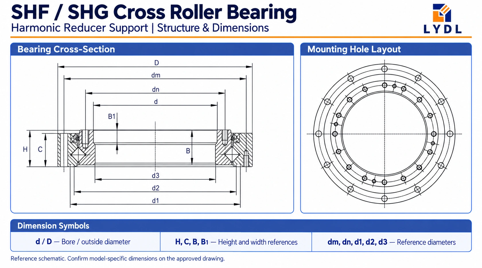
| Reference feature | Value |
|---|---|
| d (mm) | 47 |
| d3 (mm) | 44.2 |
| D (mm) | 80 |
| H (mm) | 17 |
| C (mm) | 16 |
| B (mm) | 16.4 |
| B1 (mm) | 6.5 |
| d1 (mm) | 68.1 |
| d2 (mm) | 64 |
| dm (mm) | 74 |
Dimensions: existing LYDL selection reference. The approved model drawing defines tolerances, variant mapping and supplied interfaces.
A service restraint can protect a connector only if its position suits the joint movement. Examine the length of free cable, the support points and the path through the flange. Provide enough information for the harness designer to assess bending and relative motion. Check that clamps and their screws do not interfere with the bearing's fastening or neighbouring moving parts.
Where the bundle pulls on the driven tool, include that force in the support-load description. Do not assume it is eliminated merely because the services pass centrally. For replacement work, inspect the previous route for wear marks and damaged protection. Explain any revised restraint or connector location so the drawing review addresses the configuration that will actually be used.
A sensor or small tool may require stable orientation, but the observed movement depends on the complete mechanism. Define runout and flange movement with a clear measurement position. Record whether services are fitted and whether external load is applied. Cable forces that vary across travel can affect running resistance without being a bearing manufacturing defect.
Agree the bearing's clearance or preload, sealing and lubrication conditions independently of the gearbox's positioning-accuracy statement. Ask for confirmed component ratings for the applied radial, axial and overturning demands. The original SHF/SHG unit references establish the comparison family, not standalone LYDL performance. The LYDL cross roller bearing range helps evaluate alternatives when the mechanism requires a different support layout.
Identify the stationary housing and driven flange connections, including access after the strain-relief hardware is fitted. Check centring registers, shoulder contact and axial clearances. The outer pitch circle is only one part of a fastening specification: hole details, thread depth, orientation and screw engagement still need the approved drawing.
During assembly, protect machined contact faces from cable sleeves, trapped particles and loose fasteners. Apply the specified tightening procedure and inspect the planned travel afterwards. Record both mechanical behaviour and service clearance. If an issue appears at one position, identify the contacting part or force source rather than adjusting the bearing specification without evidence.
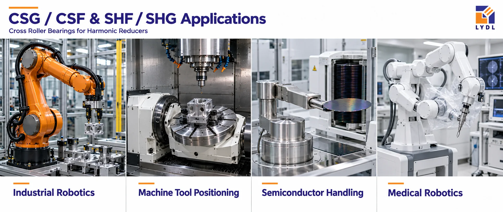
In industrial robotics, a comparable position can support a wrist carrying a sensor, gripper and service bundle. Machine-tool equipment may use a small orienting mechanism with electrical feedback connections. Semiconductor handling can involve articulated inspection heads with pneumatic or vacuum services. Medical positioning equipment may need protected instrument cables, with independent device qualification.
The application graphic depicts these broader fields. It is not evidence of a specific size-17 installation or a certification of cable life, cleanroom performance or device suitability. Match both the mechanical interfaces and the service-route requirements for the actual equipment.
Record the model and drawing revision with measurements of the agreed bore steps, seating features and mounting interfaces. Specify rotational checks and their conditions. Preserve the harness section and restraint layout with the assembly documentation, particularly if they differ from the earlier machine configuration. Review LYDL company and manufacturing information for supplier background.
For delivery, discuss individual separation, corrosion protection and restraints that avoid damage to locating surfaces. The inspection and packaging picture should represent the described activities honestly. A generic packing photograph may explain a method, but it cannot establish model-specific inspection results or confirm the suitability of the final routed assembly.

Include connectors, sleeves, bend requirements and movement at the restraints. Check the whole passage at the travel extremes. A nominal bundle diameter does not show the installation envelope or the space required for bending and service access.
They identify different axial features in the reference section. Verify each at its drawn location and compare the complete mating stack-up. Similar values do not make the symbols interchangeable or define the overall height twice.
Its attachment and cable tension can create forces on the driven equipment. Describe the restraint positions and operating movement in the load review. Central routing does not automatically remove those forces from the support mechanism.
Record the test with clearly stated routing and mounting conditions, and compare relevant configurations where appropriate. Inspect travel-dependent contact and cable tension. Bearing checks should remain distinguishable from the behaviour introduced by fitted services.
Document wear marks, damaged sleeves, restraint locations and connector loading as well as the bearing interfaces. State any intended routing changes. This helps avoid approving a replacement against an assembly arrangement that is no longer being retained.
Use LYDL technical enquiry to provide the size-17 section, service-bundle layout and restraint locations. Include the reducer reference, quantity and required mounted measurements. LYDL can review the bearing interface with the actual movement and routing conditions clearly described.
LYDL supplies its own bearings. Referenced brand names identify comparison families; agreed drawings and order specifications define supplied performance.