

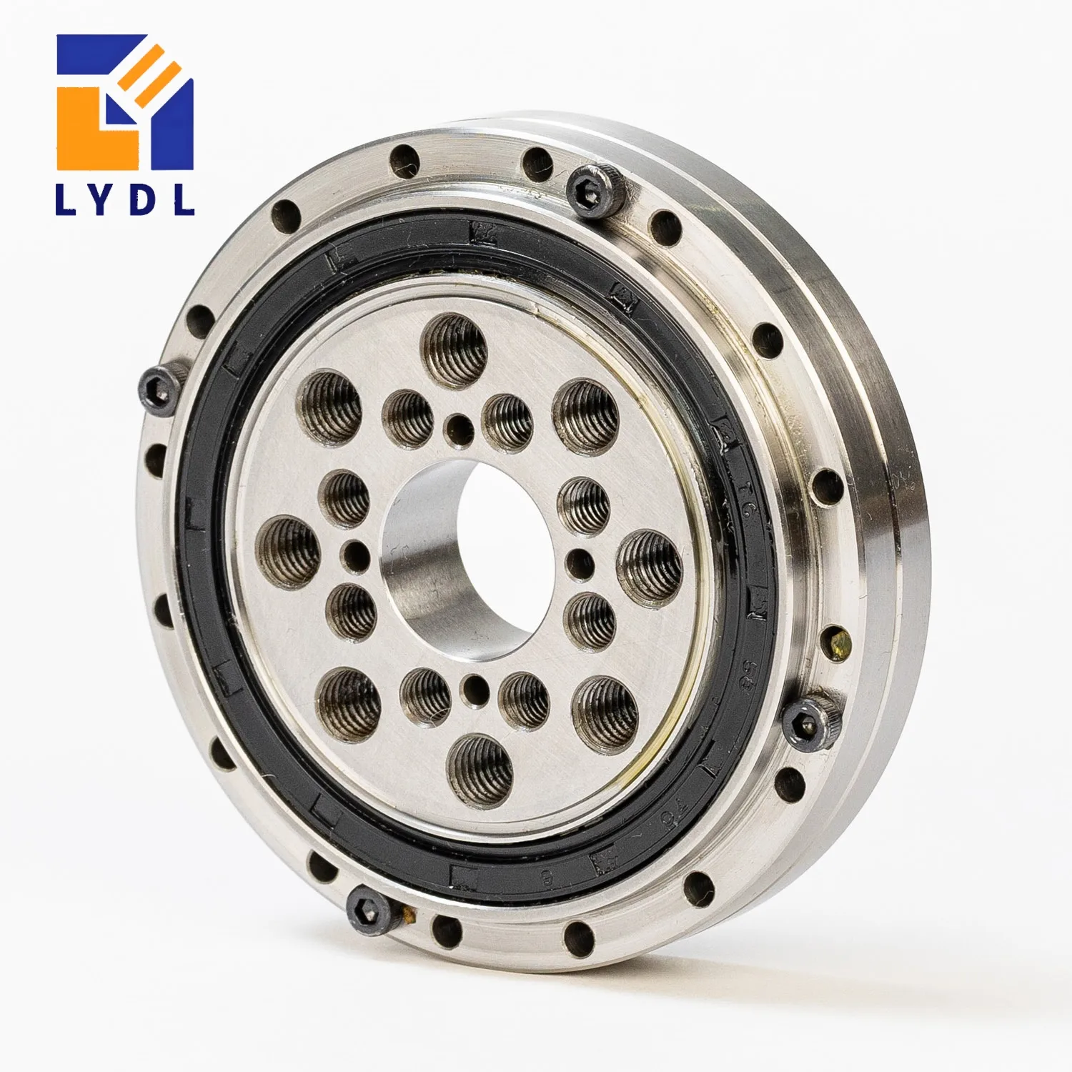
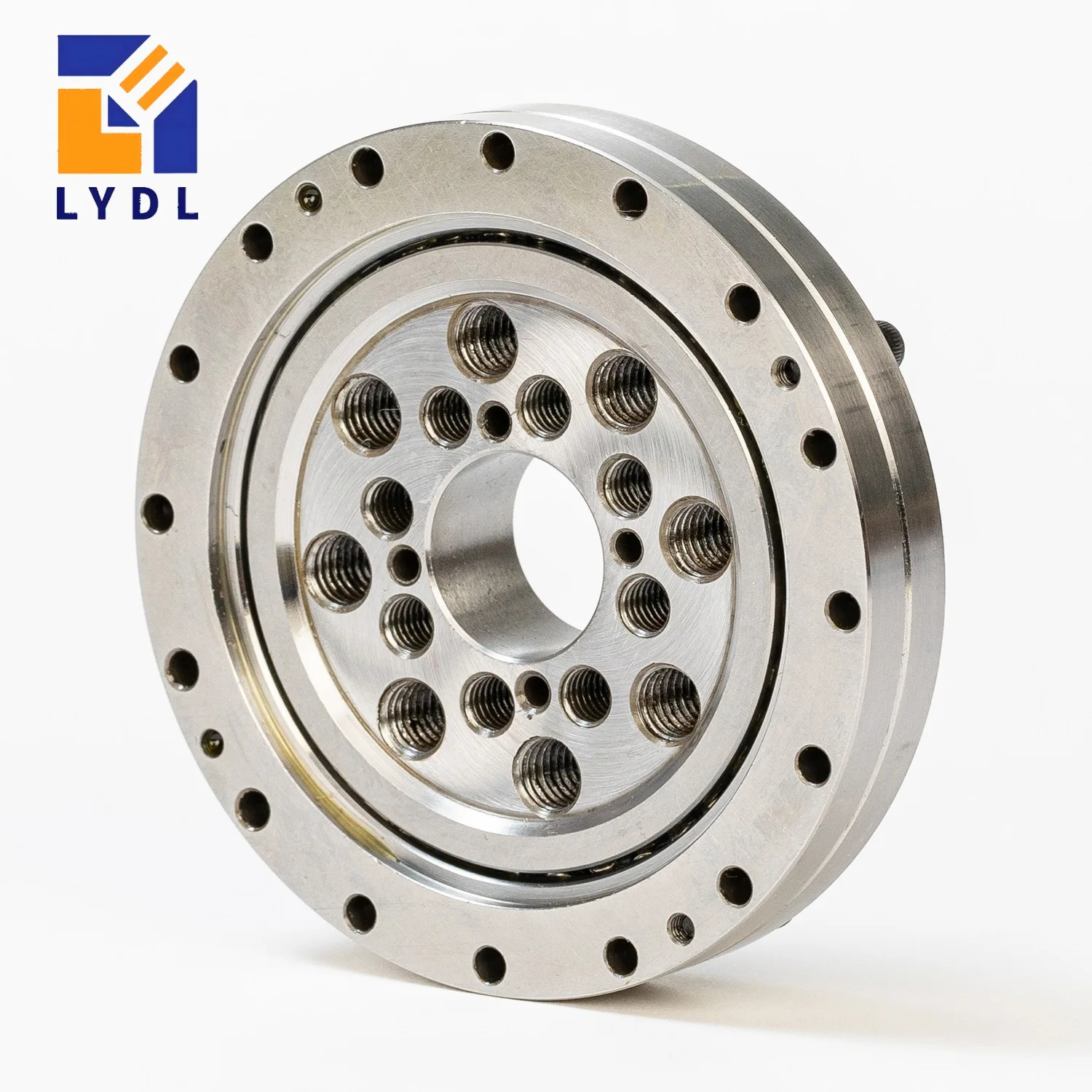
CSG / CSF cross roller bearings support the output flange in compatible harmonic reducer assemblies. Use this guide to compare reference dimensions, mounting interfaces and selection requirements. Start with the complete reducer designation and compare its bearing drawing with your assembly. The series table identifies candidates; the agreed LYDL drawing defines the supplied component.
Use the CSG / CSF product catalogue to browse this family. Cylindrical rollers arranged in alternating directions allow a compact bearing position to accommodate radial force, axial force and overturning moment. Its installation must provide suitable support and alignment for the loads involved.
Harmonic Drive describes CSG-2UH as a high-torque gear unit and CSF-2UH as a standard-torque alternative; both incorporate a cross roller output bearing and flange. The unit designation does not establish a replacement bearing’s load rating. Check the suffix, size, ratio, revision and any lightweight designation. [1, 2]
The output support bearing carries loads from the attached mechanism. The flexible bearing at the wave generator performs a different function and requires its own identification. If your assembly has a large central service passage, also review the SHF / SHG bearing selection guide; confirm the actual interface rather than selecting by appearance.
The section view below shows the bearing arrangement and axial steps; the front view illustrates mounting features. In this LYDL reference, d denotes the central bore, D the outside diameter and H the overall axial dimension. Symbols C, B, H2 and C1 identify additional axial details. dm, dn and dL identify mounting pitch circles; d1, d2, D1 and D2 identify other diameters. Preserve letter case when checking a drawing.
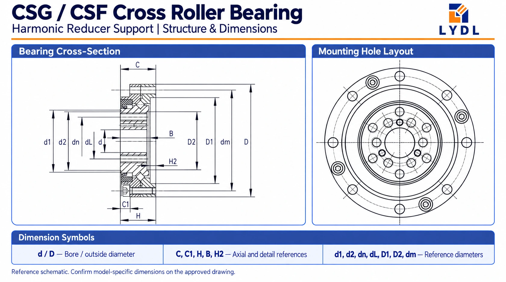
The illustration explains the family layout. Hole counts, fastener positions and section details vary with the selected model and interface. Read its symbols alongside the numerical tables, then use the model-specific drawing for tolerances and manufacture.
The following dimensions reproduce the existing LYDL selection references in millimetres. Read the model number as a family size reference, not a bore diameter. Parenthesised values identify alternative entries in the source table; they are not dimensional tolerances. Their exact configuration must be identified on the matching drawing.
| Model reference | d | D | H | C | B | H2 | Drawing |
|---|---|---|---|---|---|---|---|
| CSG/CSF-14 | 11(9) | 55 | 16.5 | 16 | 13.5 | 2.5 | Drawing |
| CSG/CSF-17 | 10 | 62 | 16.5 | 16 | 13.5 | 2.5 | Drawing |
| CSG/CSF-20 | 14 | 70 | 16.5 | 16 | 13.5 | 2.5 | Drawing |
| CSG/CSF-25 | 20 | 85 | 18.5 | 18 | 16.5 | 2 | Drawing |
| CSG/CSF-32 | 26 | 112 | 22.5 | 21.5 | 19 | 3 | Drawing |
| CSG/CSF-40 | 32(24) | 126 | 24 | 22.5 | 21.5 | 2.5 | Drawing |
| CSG/CSF-50 | 40(32) | 157 | 31 | 30 | 28 | 3 | Drawing |
| CSG/CSF-65 | 52(44) | 210 | 39 | 37 | 35 | 4 | Drawing |
| Model reference | D1 | D2 | d1 | d2 | Drawing |
|---|---|---|---|---|---|
| CSG/CSF-14 | 41.8 | 28 | 29.8 | 28.4 | Drawing |
| CSG/CSF-17 | 49 | 34 | 36 | 33.8 | Drawing |
| CSG/CSF-20 | 56.5 | 40 | 43 | 40.2 | Drawing |
| CSG/CSF-25 | 67 | 51 | 55.3 | 52.6 | Drawing |
| CSG/CSF-32 | 90 | 64 | 74 | 68.6 | Drawing |
| CSG/CSF-40 | 105 | 86 | 86 | 81.2 | Drawing |
| CSG/CSF-50 | 131.6 | 98 | 108 | 102.6 | Drawing |
| CSG/CSF-65 | 176 | 130 | 138 | 132.6 | Drawing |
| Model reference | Outer PCD dm | Outer holes | Inner PCD dn | Inner holes | Additional PCD dL | Additional holes | Drawing |
|---|---|---|---|---|---|---|---|
| CSG/CSF-14 | 49 | 8-Φ3.5 | 23 | 6-M4 | 17(14.5) | 6-M4(M3) | Drawing |
| CSG/CSF-17 | 56 | 10-Φ3.5 | 27 | 6-M5 | 19 | 6-M5 | Drawing |
| CSG/CSF-20 | 64 | 12-Φ3.5 | 32 | 8-M6 | 24 | 8-M5 | Drawing |
| CSG/CSF-25 | 79 | 16-Φ3.5 | 42 | 8-M8 | 30 | 8-M6 | Drawing |
| CSG/CSF-32 | 104 | 16-Φ4.5 | 55 | 8-M10 | 40 | 8-M10 | Drawing |
| CSG/CSF-40 | 117 | 20-Φ5 | 68 | 8-M10 | 50 | 8-M10 | Drawing |
| CSG/CSF-50 | 147 | 16-Φ5.5 | 84 | 8-M14 | 60 | 8-M14 | Drawing |
| CSG/CSF-65 | 198 | 20-Φ6.5 | 110 | 8-M16 | 80 | 8-M16 | Drawing |
For example, size 20 lists a 14 mm bore, 70 mm outside diameter and 16.5 mm overall height. Also verify locating steps, bolt circles, threads and assembly requirements. C1 appears in the structure reference but is unspecified in the numerical table.
For context, the original CSG/CSF-2UH catalogue lists the following output-bearing reference values. They describe that manufacturer’s specified assembly, not verified LYDL replacement ratings. C is the basic dynamic rating and C0 the basic static rating; dimensional C (mm) is a separate axial measurement. Mc is the catalogue’s allowable moment under its stated conditions. [3]
| Original unit size | C (kN) | C0 (kN) | Mc (Nm) |
|---|---|---|---|
| 14 | 4.74 | 6.07 | 41 |
| 17 | 5.29 | 7.55 | 64 |
| 20 | 5.78 | 9.00 | 91 |
| 25 | 9.60 | 15.1 | 156 |
| 32 | 15.0 | 25.0 | 313 |
| 40 | 21.3 | 36.5 | 450 |
| 50 | 34.8 | 60.2 | 759 |
| 65 | 55.6 | 103 | 1860 |
A moment check does not replace a bearing-life calculation. For a simple perpendicular force, moment is force multiplied by its lever arm: a 100 N force acting 0.10 m from the support creates 10 Nm. Actual selection must account for the complete load geometry, combined forces, duty cycle and mounting stiffness. Obtain the supplied bearing’s confirmed ratings before applying a reference calculation.
Specify the required radial and axial runout at the working flange, along with the measurement method and mounted condition. Clearance or preload, running torque, seals and lubricant must suit the mechanism. Complete-reducer positioning accuracy is a system specification and cannot be assigned to a replacement bearing as its accuracy grade.
Inspect mating faces for burrs, contamination and damage. Follow the specified installation sequence and bolt torque. Check rotation after clamping; increased running resistance can indicate distortion or interference. Compare constructions in the cross roller bearing range.
These four fields illustrate output-support applications. Select the bearing for the actual axis and loads, rather than the equipment category.
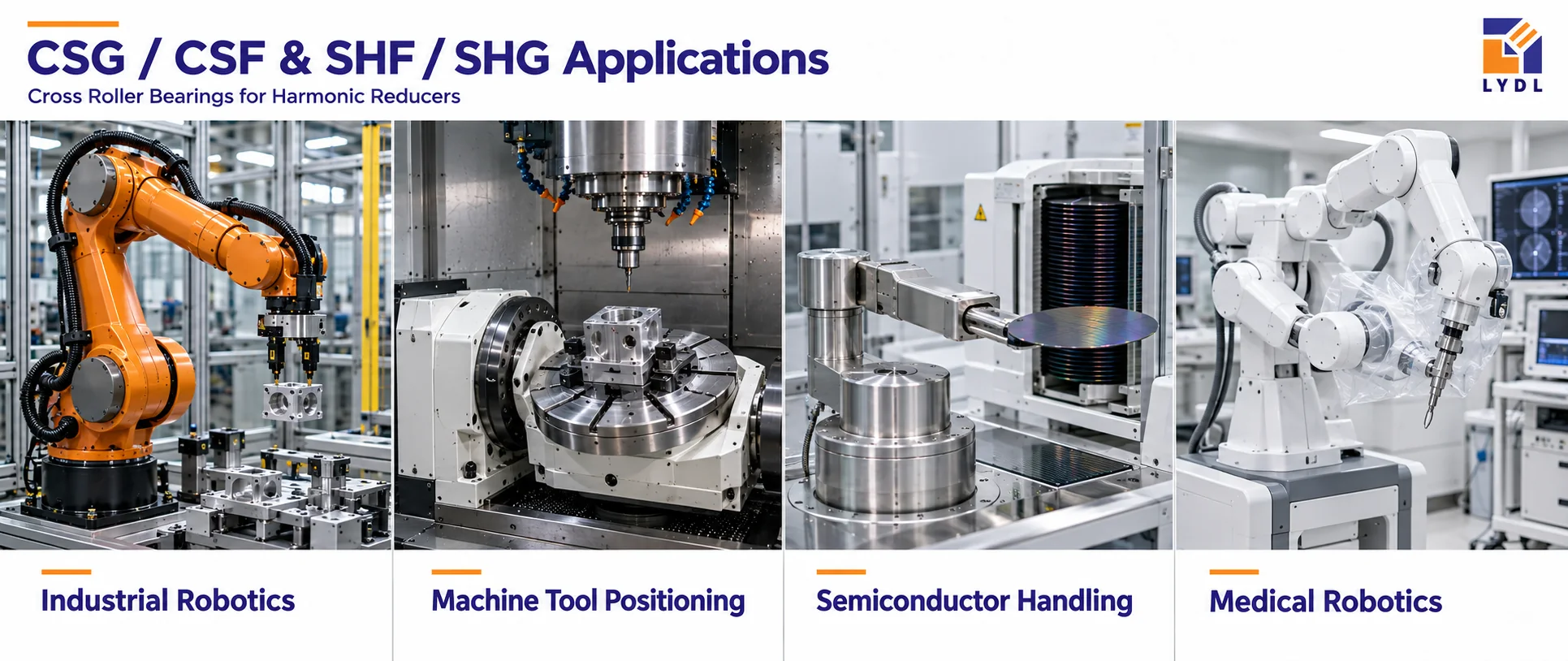
Agree the inspection scope with the order: critical dimensions, hole interfaces, runout, clearance or preload, and running behaviour where specified. A report should identify the supplied part and drawing revision. Discuss corrosion protection, protective wrapping, individual packing and transport restraint with LYDL. Packaging needs to protect machined faces and prevent movement during the intended shipment. Learn about LYDL manufacturing and inspection.

The shared size number provides a starting point. Compare the complete unit designation and bearing drawing, including registers, flange steps, holes and required performance. Confirm the replacement against those requirements before ordering.
The LYDL table contains alternative reference entries. The bracketed figure is not a tolerance or an optional machining allowance. Request the drawing identifying which configuration uses each value, and avoid combining dimensions from different variants.
A lightweight suffix identifies a unit configuration requiring its own review. Match the relevant housing and output-flange interfaces, fastening details and drawing revision. The family name alone does not confirm compatibility.
Include the external forces and overturning moment acting at the output, together with speed and duty cycle. Gear transmission torque and bearing support capacity describe different loading requirements, so both need appropriate checks.
Send the bearing and housing drawings, photographs of both mating faces, measured pilot diameters, axial steps and hole details. Identify the interfering feature and existing bolt arrangement so the review addresses the interface directly.
Contact LYDL for CSG / CSF bearing selection with your complete model, drawing, quantity, load case and delivery destination. State the accuracy, inspection and packing requirements that matter to your project. For replacement work, include the original component’s identification; for a new assembly, share the available envelope and mounting design.
LYDL supplies its own bearings. Other manufacturers’ names identify technical reference families; supplied dimensions, ratings and acceptance criteria follow the agreed LYDL specification.