

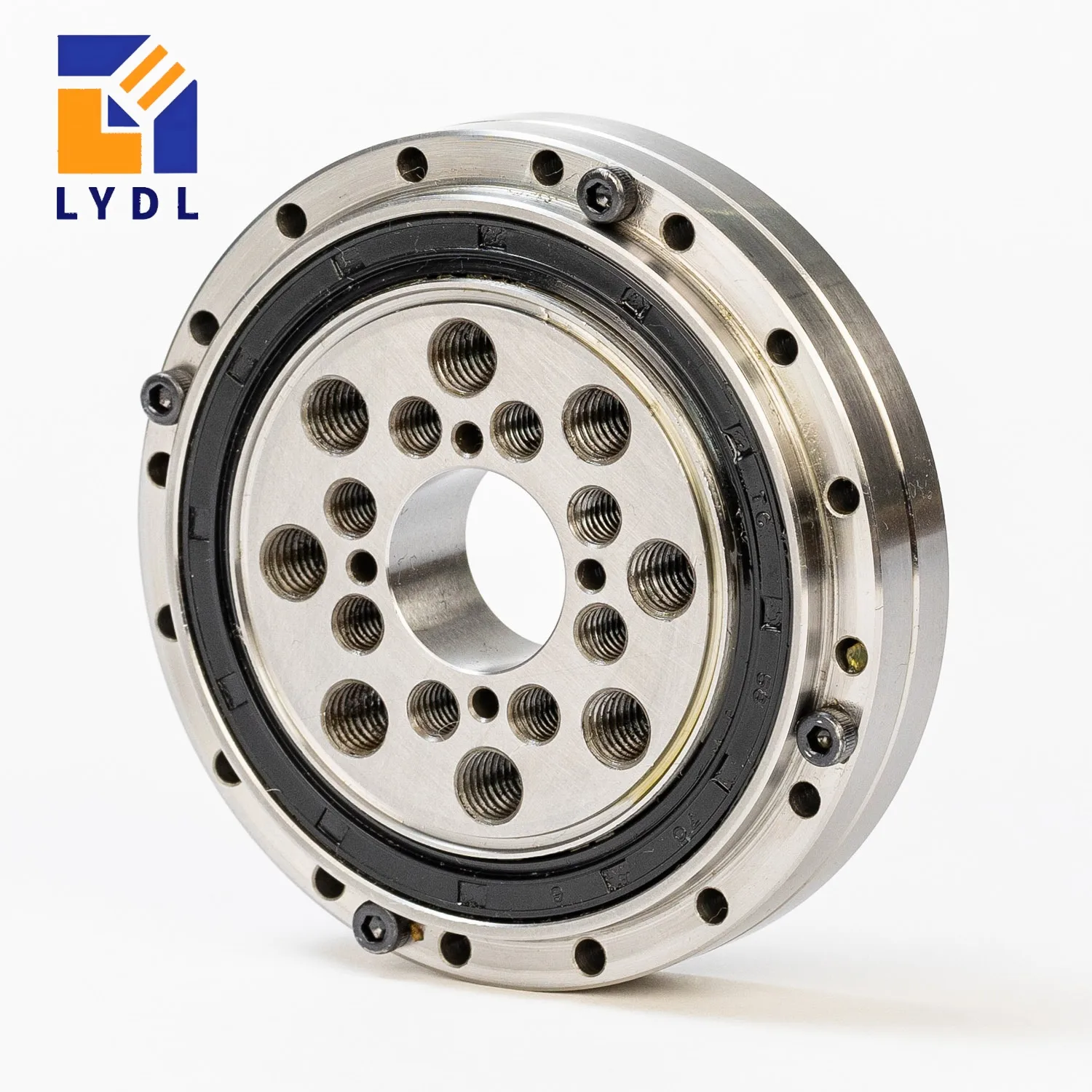
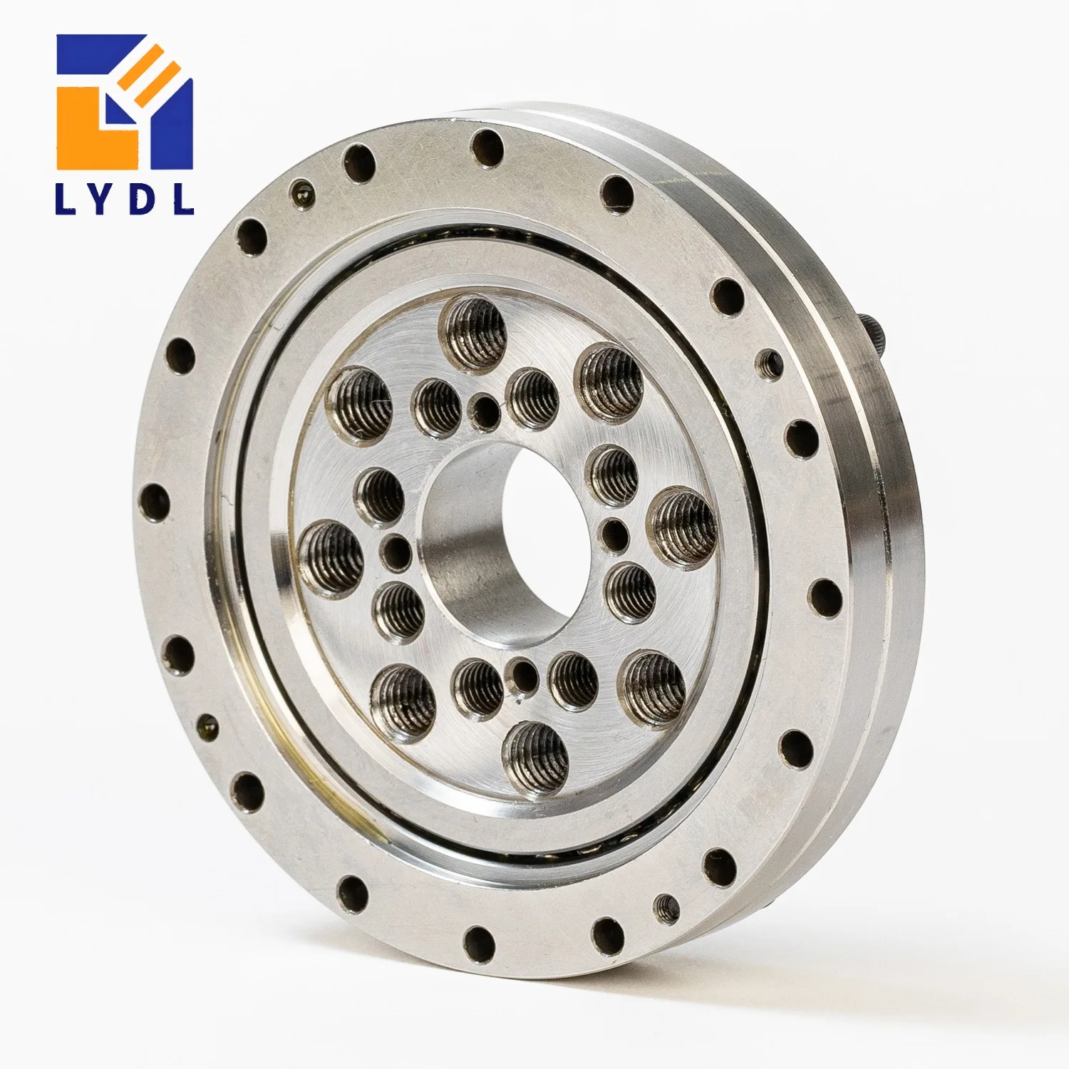
CSG-20 / CSF-20 cross roller bearing selection combines a 14 mm bore, 70 mm outside diameter and 16.5 mm overall height with a model-specific flange review. The LYDL dimensions make this reference easy to screen for a compact indexing mechanism, but the working cycle and process-force path still determine the support requirements. This guide focuses on what happens between positioning, contact and release.
Compare this model with the CSG / CSF selection guide before confirming the interface.
An indexing station does more than rotate a fixture between positions. It may accelerate, stop, dwell under load and resist a force while a tool engages the workpiece. Describe those stages separately. Include the fixture, workpiece and attachments, then identify which process forces actually pass through the bearing. An externally supported tool may have a different load path from one carried directly by the output flange.
Do not infer a permissible indexing rate from the bearing dimensions. The motor, reducer, inertia and bearing operating conditions all require consideration. For a replacement, obtain the original configuration and note whether the process has changed since installation. A higher fixture mass or longer tooling offset may invalidate assumptions that were adequate for the earlier duty.
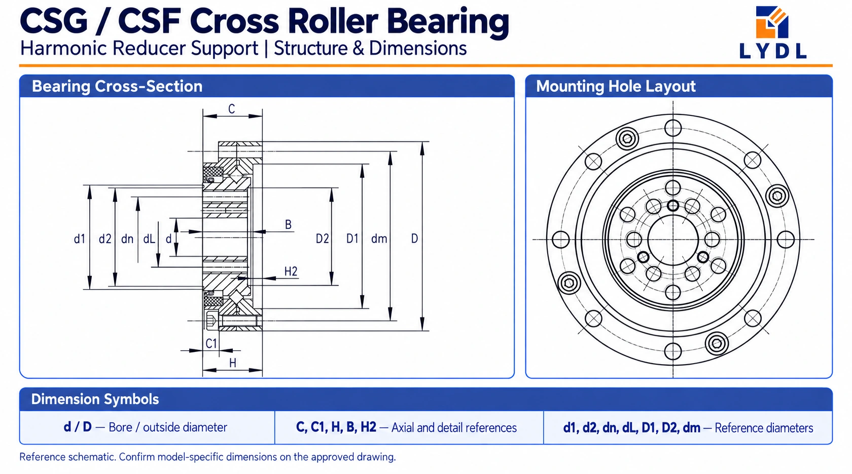
The reference section uses d, D and H for bore, outside diameter and overall axial size. The remaining section dimensions C = 16 mm, B = 13.5 mm and H2 = 2.5 mm identify specific axial details. Read D1, D2, d1 and d2 at their marked surfaces. Dimension symbols should remain visible in the page text so the drawing can be interpreted without guessing from its appearance.
At dm = 64 mm, the outer entry lists twelve 3.5 mm holes. The inner entry is eight M6 holes at dn = 32 mm; the additional interface lists eight M5 holes on dL = 24 mm. These entries are not substitutes for each other. Establish their mating parts and engagement depths. The CSG / CSF bearing category helps locate related models when a different envelope is needed.
| Reference feature | Value |
|---|---|
| d (mm) | 14 |
| D (mm) | 70 |
| H (mm) | 16.5 |
| C (mm) | 16 |
| B (mm) | 13.5 |
| H2 (mm) | 2.5 |
| D1 (mm) | 56.5 |
| D2 (mm) | 40 |
| d1 (mm) | 43 |
| d2 (mm) | 40.2 |
| Outer PCD dm (mm) | 64 |
| Outer fixing holes | 12-Φ3.5 |
| Inner PCD dn (mm) | 32 |
| Inner fixing holes | 8-M6 |
| Additional PCD dL (mm) | 24 |
| Additional fixing holes | 8-M5 |
Dimensions: existing LYDL selection reference. The approved model drawing defines tolerances, variant mapping and supplied interfaces.
A flange that accepts the screws may still sit incorrectly on its register. Measure the centring surfaces and shoulder positions, then compare the mating recess and any relief around the bearing. Confirm which faces carry axial contact and whether the driven fixture clears the remaining steps. Review the resulting axial position of the workpiece, not just the bearing's overall height.
Inspect the actual housing when replacing an older part. Wear, burrs or damage can affect a new bearing even if its drawing matches. Do not compensate for an uncertain seat by choosing a different nominal bearing dimension. Resolve the condition of the mating components and document any modification before accepting a replacement specification.
The original 2UH output-bearing figures shown below are associated with the manufacturer's stated assembly and catalogue conditions. Their C and C0 symbols identify dynamic and static load ratings, measured here in kN; dimensional C in the section remains a length in millimetres. Mc describes the catalogue moment reference. None of those labels is a transmission-torque value for the bare LYDL bearing.
For the indexing station, calculate external moments using the actual force locations and directions. Add the varying radial and axial demands and review life over the intended motion history. An occasional severe process event may be important even if the average cycle appears light. Confirm the supplied bearing's performance before relying on an original assembly comparison.
| Reference feature | Value |
|---|---|
| Basic dynamic load C (kN) | 5.78 |
| Basic static load C0 (kN) | 9 |
| Catalogue moment Mc (Nm) | 91 |
Harmonic Drive catalogue, printed page 33, Table 30. Source load units ×10² N converted to kN. Confirm configuration and rated conditions before calculation.
Specify where runout will be measured: at the bearing face, fixture register or working radius. Those measurements can have different practical consequences. A long fixture can magnify angular movement at the workpiece. State the mounted condition and load during acceptance, and distinguish measurement repeatability from the accuracy of the complete indexing system.
Prepare the seats, align the intended registers and apply the approved fastening sequence. Check running behaviour after the fixture is attached as well as after the bearing alone is clamped. Changes can expose a distorted bracket or bolt interference. Compare other constructions in the LYDL cross roller bearing range when the mechanism needs a different support arrangement; avoid selecting solely by the shared reducer size number.
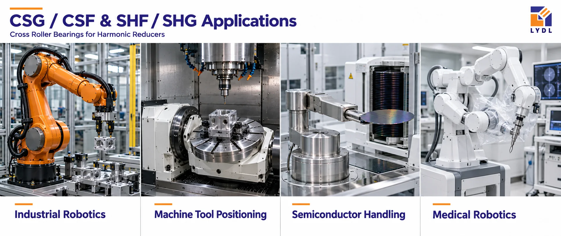
For industrial robotics, the relevant position could be a compact tool-changing or orienting flange. In machine-tool equipment, it may be an indexing attachment whose cutting or probing forces have been defined. Semiconductor handling can involve a rotary transfer stage with frequent moves and dwell periods. Medical robotics may involve a controlled positioning joint with device-specific validation.
The application image provides context for those positions. It is an illustration of possible equipment fields, not evidence of this model's installed capacity. Environmental qualification, lubrication compatibility and any regulatory acceptance belong to the particular machine design.
Request a report covering the agreed bore and flange references, fixing details and rotational acceptance. Identify the fixture register as a critical feature if it determines the workpiece position. Attach the drawing revision to the purchase information so future replacements use the same reference. The LYDL company and manufacturing information can support the supplier review alongside the technical documents.
Packing should protect seating faces and keep the component from striking other goods in transit. Discuss wrapping and restraint appropriate to the transport route. The inspection and packaging photograph should reflect real checks and protection; it should not imply that every order receives tests or equipment demonstrations that have not been agreed.

Describe acceleration, stopping, dwell and process-contact stages. Include the workpiece and fixture geometry, force directions and lever arms. Identify whether the tool force reaches the output support or is carried through a separate structure.
They belong to different reference interfaces and pitch circles. Establish each mating connection from the drawing. Matching the quantity of holes does not make their threads, positions or mechanical function equivalent.
It provides an envelope reference only. Permissible motion depends on the actual bearing configuration, loading, lubrication and complete drive design. Submit the output-speed history and reversal cycle for the component review.
That is where a positioning error may affect the process. State the radius, load and mounted condition. A measurement at the bearing face alone may not capture the behaviour of the attached fixture and its support structure.
Reassess the support loads, moment, life and mounting conditions before assuming suitability. A changed tooling offset or contact force can alter the requirement even when the reducer and nominal indexing sequence remain unchanged.
Request a size-20 review through LYDL technical enquiry with the fixture drawing, working-cycle stages and process-force locations. Include the exact CSG or CSF unit reference, quantity and required inspection results so the quotation addresses the complete output-support interface.
LYDL supplies its own bearings. Referenced brand names identify comparison families; agreed drawings and order specifications define supplied performance.