

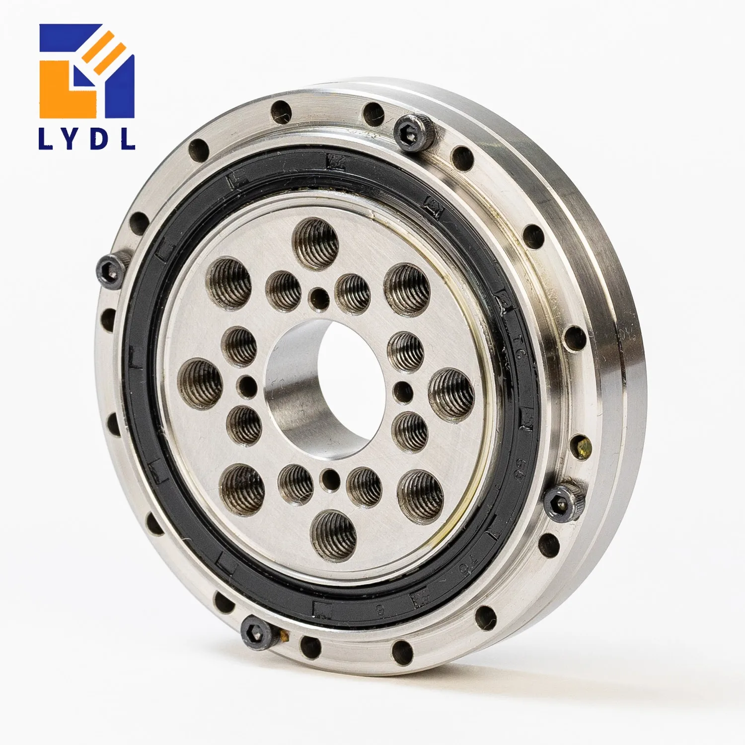
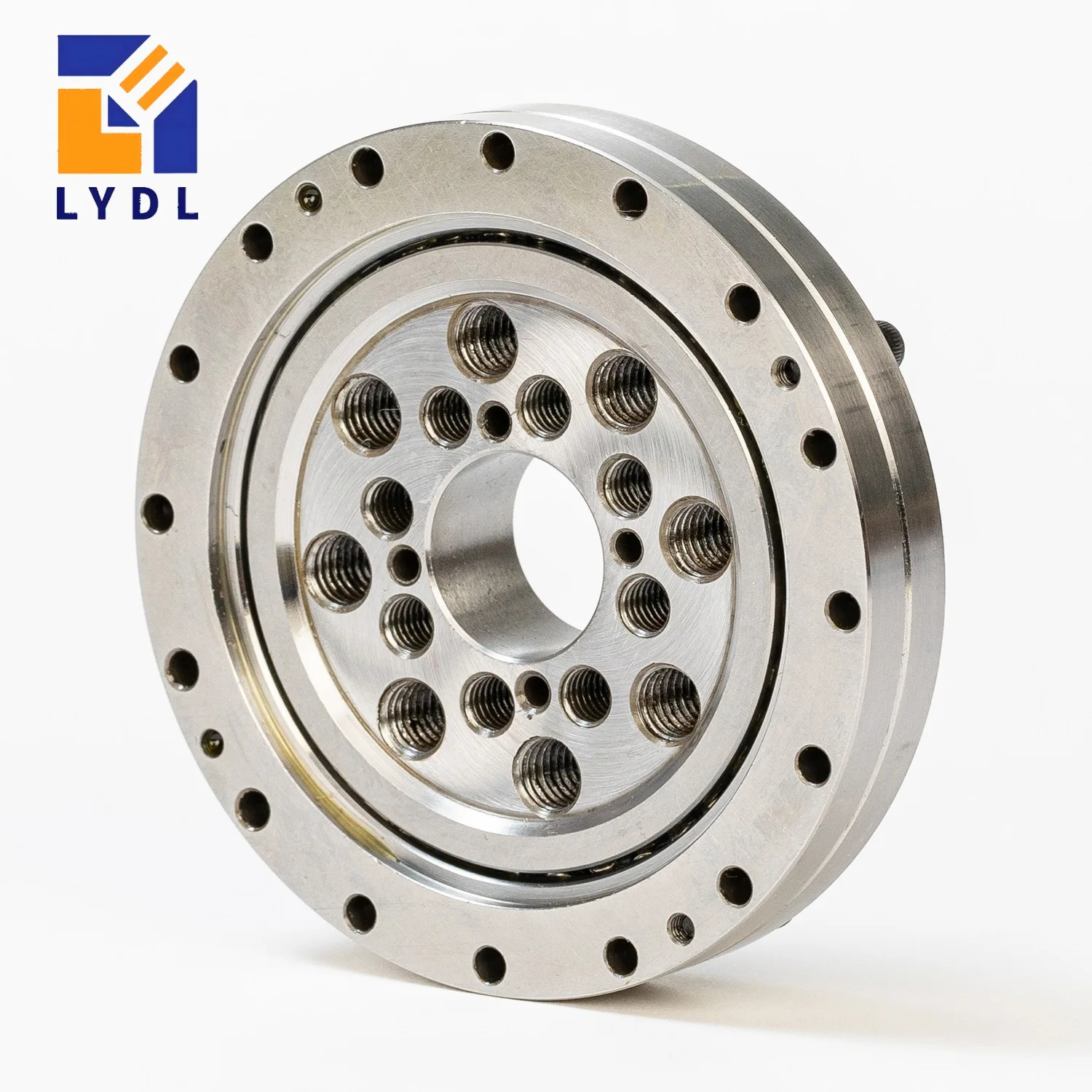
CSG-65 / CSF-65 cross roller bearing references describe a 210 mm outside diameter and 39 mm overall height, with bore entries of 52(44) mm. A larger output-support interface requires attention to the surrounding structure, assembly access and handling method as well as its numerical dimensions. This size-65 guide is intended for a drawing-led review of a positioning flange or comparable driven mechanism.
Compare this model with the CSG / CSF selection guide before confirming the interface.
Start with the assembly section and the geometry of the driven equipment. Identify the fixed housing, output flange and components that introduce force into the bearing. Show supported masses, process loads and the distance of each load from the support location. For a positioning mechanism, include the demanding orientations and any acceleration or stopping event defined by the machine design.
An increased interface diameter does not prove that the surrounding housing provides adequate stiffness. Review flange contact, registers and the attachment to the machine frame. If the enquiry concerns an upgraded payload, record the difference from the original design. The bearing selection should address the complete load path rather than simply choosing the largest listed reference.
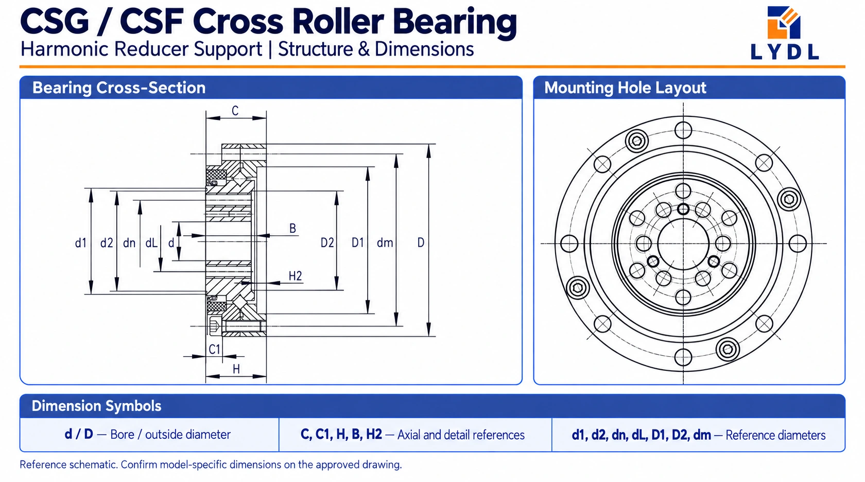
The section uses d = 52(44) mm for alternative bore references and D = 210 mm for the outer envelope. H = 39 mm, C = 37 mm, B = 35 mm and H2 = 4 mm locate axial details. Resolve the bore configuration with the complete reducer identification before preparing the mating shaft or adapter. Parentheses in this source are not an allowable tolerance band.
Secondary diameters D1 = 176 mm, D2 = 130 mm, d1 = 138 mm and d2 = 132.6 mm need association with their drawn features. Check the axial position and function of each mating surface. The CSG / CSF bearing category supplies the family overview; a controlled model drawing establishes which dimensions and contacts belong to the component being ordered.
| Reference feature | Value |
|---|---|
| d (mm) | 52(44) |
| D (mm) | 210 |
| H (mm) | 39 |
| C (mm) | 37 |
| B (mm) | 35 |
| H2 (mm) | 4 |
| D1 (mm) | 176 |
| D2 (mm) | 130 |
| d1 (mm) | 138 |
| d2 (mm) | 132.6 |
| Outer PCD dm (mm) | 198 |
| Outer fixing holes | 20-Φ6.5 |
| Inner PCD dn (mm) | 110 |
| Inner fixing holes | 8-M16 |
| Additional PCD dL (mm) | 80 |
| Additional fixing holes | 8-M16 |
Dimensions: existing LYDL selection reference. The approved model drawing defines tolerances, variant mapping and supplied interfaces.
The outer interface lists twenty 6.5 mm holes on dm = 198 mm. Eight M16 threads are listed at dn = 110 mm, with a further eight-M16 reference at dL = 80 mm. Confirm hole positions, thread depths, screw access and the intended mating connections. The family schematic should not be treated as a universal bolt pattern for every supplied configuration.
Plan how the flange will be aligned and secured without using bolts to drag an uncertain register into place. Review clearance for tools and fasteners with the surrounding equipment installed. Determine contact faces and any relief features on the full assembly drawing. If hardware or adapters are redesigned, include those changes in the interface review instead of relying on the previous component's visual similarity.
Use the original 2UH catalogue values below as explicitly labelled assembly references. Their dynamic and static ratings and allowable-moment reference do not establish the supplied LYDL bearing's performance. Confirm the appropriate component data and rated conditions in the order review. Complete gear-unit torque and mass remain separate quantities from bare-bearing support capacity and handling mass.
For a large positioning flange, describe loads at each relevant orientation and over the cycle. Include process forces, offsets and severe events, together with required life and motion. A static holding case does not describe the entire rotating duty. Different load states may govern maximum-load assessment, life or assembly deflection; the engineering review should keep those checks distinct.
| Reference feature | Value |
|---|---|
| Basic dynamic load C (kN) | 55.6 |
| Basic static load C0 (kN) | 103 |
| Catalogue moment Mc (Nm) | 1860 |
Harmonic Drive catalogue, printed page 33, Table 30. Source load units ×10² N converted to kN. Confirm configuration and rated conditions before calculation.
Confirm the actual component mass and any approved handling method before installation. Do not use a mounting hole as an assumed lifting point without a verified instruction. Provide suitable support while aligning the component and protect the locating faces from contact damage. Keep temporary handling fixtures separate from the final mounting requirements.
Specify runout, flange movement and running behaviour with the measurement location and mounted condition. Check the housing and contacts before clamping, then inspect the assembled support according to the agreed procedure. A large working radius can make angular movement significant at the driven equipment. Review the LYDL cross roller bearing range if the system needs another support arrangement, and define the interface changes before ordering an alternative.
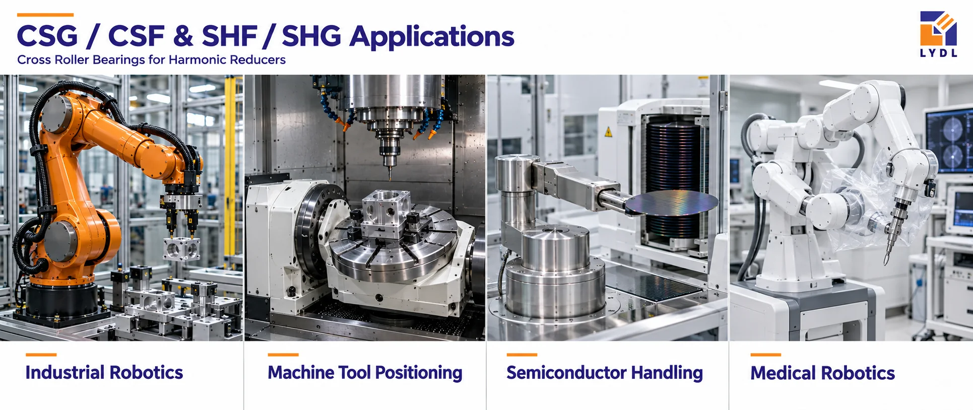
Industrial robotics can involve a larger driven joint or process-tool support, where arm geometry must be evaluated. Machine-tool positioning can involve an orienting mechanism carrying a defined fixture and process load. Semiconductor equipment may use a larger articulated transfer assembly with environmental requirements stated separately. Medical positioning equipment may employ similar mechanical concepts, with independent device validation.
These descriptions identify possible support roles, not qualified size-65 installations. The application illustration does not establish a permissible payload or certify suitability. Assess the particular assembly against its drawings, loads and confirmed component specification.
Identify the selected bore configuration and all critical registers in the inspection scope. Agree measurements for the mounting interfaces and rotational characteristics, along with the report's part and drawing identification. Where assembly testing is required, define its equipment, conditions and acceptance criteria separately from loose-component checks. See LYDL company and manufacturing information for company information relevant to procurement.
Discuss protected faces, corrosion precautions and transport restraint appropriate to the actual component and shipment. Confirm how the package will be handled and opened without damaging the bearing. An image can explain a representative packing method, but the supplied part's mass, restraints and inspection results must be recorded for the order rather than inferred from the picture.

Payload depends on load geometry, motion, mounting stiffness and the supplied bearing ratings. Compare the demanding force and moment cases for the mechanism. A larger envelope alone is not a complete capacity assessment or approval of the surrounding structure.
Only use a handling method approved for the actual component. Thread size and hole location do not establish a rated lifting point. Confirm the supplied mass, suitable fixtures and protection of the locating faces before installation.
Identify the configuration associated with each source-table alternative. Match the full reducer and approved drawing before choosing a bore. The bracketed value is not a tolerance and should not be combined with unrelated variant dimensions.
Movement at the driven equipment can differ from a reading close to the bearing. State the working radius, applied load and installed condition. This helps relate the acceptance check to the mechanism's actual positioning requirement.
Include rotating, accelerating and stopping stages as applicable, plus process and severe events. Maximum-load and life checks may depend on different conditions. Define the cycle and required service life before confirming the component and installation.
Send the size-65 assembly section, variant identification and working-cycle loads through LYDL technical enquiry. Add the proposed handling method, quantity and required reports. LYDL can then review the component interfaces, acceptance plan and packing requirements before quotation.
LYDL supplies its own bearings. Referenced brand names identify comparison families; agreed drawings and order specifications define supplied performance.