

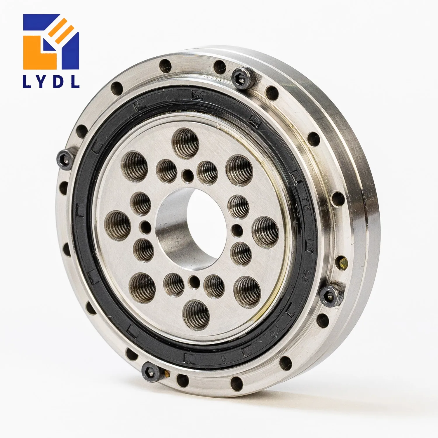
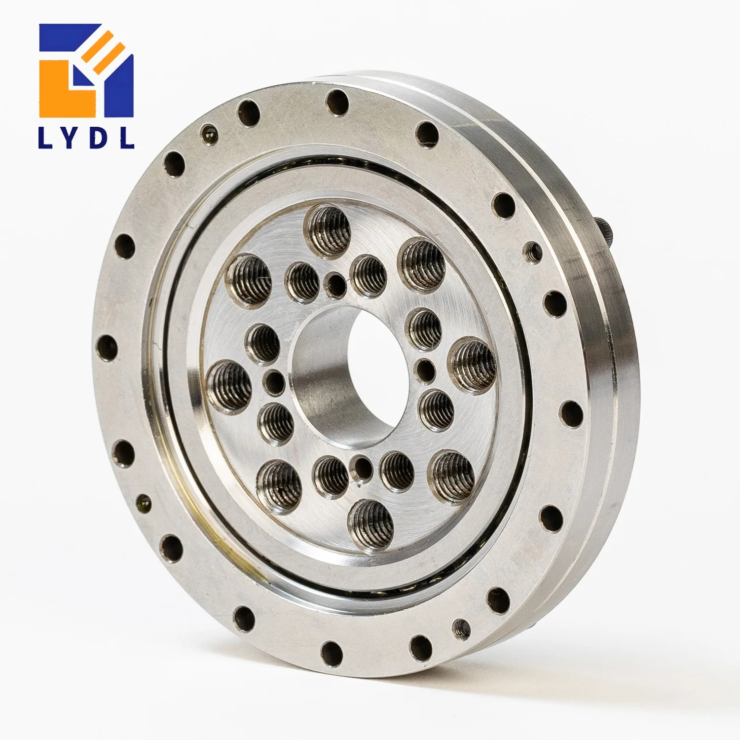
CSG-25 / CSF-25 cross roller bearing references use a 20 mm bore, 85 mm outside diameter and 18.5 mm overall height. For an articulated wrist or overhung tool flange, dimensional fit is only the first decision. The position of the tool, changing arm orientation and mounting stiffness determine what must be checked before a replacement or new component is specified.
Compare this model with the CSG / CSF selection guide before confirming the interface.
Include the tool plate, gripper, workpiece and any adapters when describing the load. A catalogue payload value for another machine cannot replace the actual mass distribution on your flange. Mark the centre of gravity and force application points relative to the bearing support. Show the wrist in the positions that produce the demanding radial, axial and overturning loads.
Also identify forces from hoses, cable restraints and process contact. These may be small individually but can change the direction or consistency of the load during movement. If the enquiry concerns a worn assembly, explain whether the tool or task has changed. The replacement review should address the current duty instead of silently carrying forward an obsolete tooling assumption.
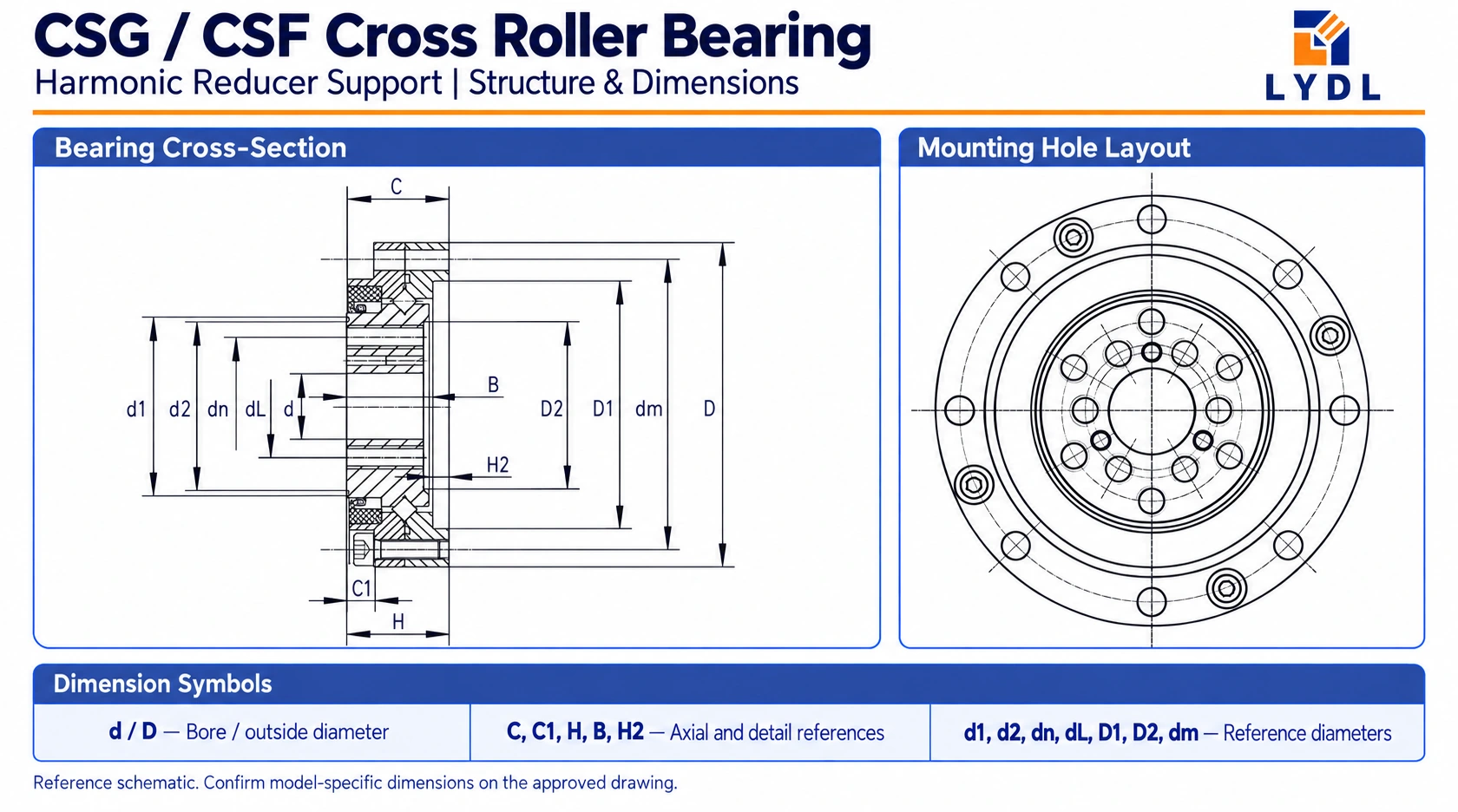
The size-25 section identifies H = 18.5 mm overall, C = 18 mm, B = 16.5 mm and H2 = 2 mm at separate axial features. Their locations matter when the tool plate sits close to the housing. Match the shoulder contact, recess depth and neighbouring clearances in a full section of the wrist. Do not infer a flush mounting condition from the overall height alone.
For the main fastening references, dm = 79 mm carries sixteen 3.5 mm holes and dn = 42 mm carries eight M8 threads. The additional dL = 30 mm entry lists eight M6 threads. Verify which part connects to each circle, plus thread depth and access. Related configurations are listed in the CSG / CSF bearing category, while the drawing establishes the exact wrist interface.
| Reference feature | Value |
|---|---|
| d (mm) | 20 |
| D (mm) | 85 |
| H (mm) | 18.5 |
| C (mm) | 18 |
| B (mm) | 16.5 |
| H2 (mm) | 2 |
| D1 (mm) | 67 |
| D2 (mm) | 51 |
| d1 (mm) | 55.3 |
| d2 (mm) | 52.6 |
| Outer PCD dm (mm) | 79 |
| Outer fixing holes | 16-Φ3.5 |
| Inner PCD dn (mm) | 42 |
| Inner fixing holes | 8-M8 |
| Additional PCD dL (mm) | 30 |
| Additional fixing holes | 8-M6 |
Dimensions: existing LYDL selection reference. The approved model drawing defines tolerances, variant mapping and supplied interfaces.
Torque transmitted about the rotation axis and overturning moment from an offset tool are different loading descriptions. A higher-torque gear-unit label does not automatically confirm the capacity of a standalone replacement bearing. Specify both the drive duty and the external loads at the output support. Harmonic Drive's CSG and CSF designations describe original gear-unit families, whose specifications must be read in their own context.
Review acceleration and deceleration with the tool's inertia, especially after a tooling change. Include holding and contact conditions as well as travel. The reference load figures below relate to the original 2UH bearing assembly; obtain the agreed LYDL performance for the supplied configuration. A force-and-lever-arm sketch helps communicate the requirement without pretending to be a complete life calculation.
The bearing can only work within the stiffness of its surrounding assembly. Review the tool plate, register, fasteners and housing together. A thin adapter or uneven support face can produce movement that may be wrongly attributed to the bearing. Specify the required flange behaviour at the actual working point and identify the load used during the measurement.
Use the intended locating surfaces to position the component and the agreed fasteners to secure it. Check that screws do not bottom out before the flange is clamped. Record rotation after the adapter is mounted. If the result changes substantially when the tool is attached, investigate the whole load path. The LYDL cross roller bearing range offers alternatives when an updated mechanism requires another support geometry.
| Reference feature | Value |
|---|---|
| Basic dynamic load C (kN) | 9.6 |
| Basic static load C0 (kN) | 15.1 |
| Catalogue moment Mc (Nm) | 156 |
Harmonic Drive catalogue, printed page 33, Table 30. Source load units ×10² N converted to kN. Confirm configuration and rated conditions before calculation.
For a wrist that accepts different tools, record which configuration is used for inspection and which represents the demanding service load. Runout at an empty flange and behaviour with an overhung tool answer different questions. Define clearance or preload, starting resistance and rotational checks with their mounting conditions. Avoid accepting a component against an unspecified universal precision grade.
Consider the intended lubrication and sealing arrangement alongside movement and environment. Do not assume that an application photograph confirms suitability for coolant, washdown or a controlled clean environment. Where a special requirement exists, document it in the drawing review and order. Consistent identification allows maintenance staff to distinguish an approved replacement from a superficially similar size-25 component.
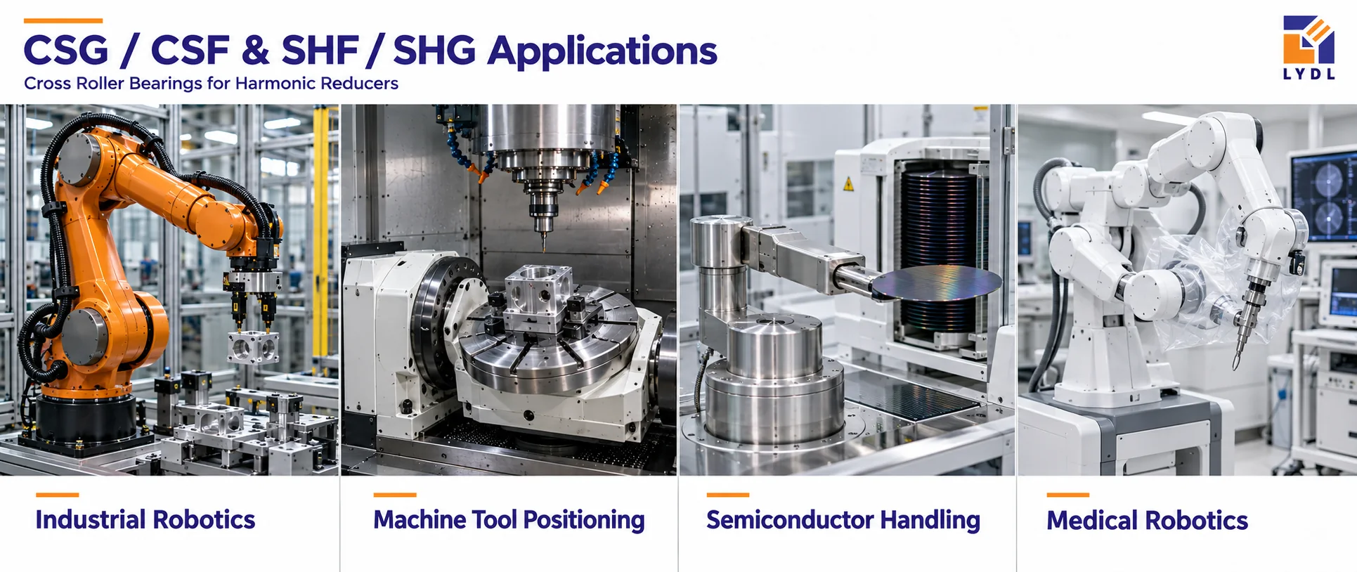
Industrial robotics may use this support position behind a wrist-mounted tool plate; evaluate the tool at changing orientations. Machine-tool positioning may involve an orienting head where process forces are explicitly traced through the flange. Semiconductor handling can involve an articulated transfer tool, with contamination requirements defined independently. Medical robotics may involve an instrument-positioning joint requiring validation as part of the complete device.
Application illustrations establish neither payload limits nor environmental qualification; use confirmed component data.
Ask for the bore, seating steps and critical fixing interfaces to be identified in the inspection scope. If tool positioning depends on an output register, state the required measurement at that surface. Attach the approved drawing and record its revision in the purchase documents. The LYDL company and manufacturing information provides supplier information for the procurement review.
Discuss protection of the register and both mating faces, with individual packing and restraint suitable for shipment. Prevent spare fasteners from contacting the machined surfaces. The proposed inspection and packaging image may show a representative arrangement only when labelled accordingly. Actual inspection results and delivery configuration should be confirmed for the order rather than inferred from a promotional image.

The force locations and inertia may change even if tool mass remains similar. Update the centre-of-gravity position, lever arms and acceleration profile. Review support loads and mounted stiffness before assuming the earlier bearing selection still applies.
The original gear-unit designation and the supplied support bearing rating are separate specifications. Compare the confirmed component ratings, configuration and installation conditions. Do not assign a gearbox torque advantage to a replacement bearing without that evidence.
Check access, relief and clearances on the complete assembly drawing. An adapter must seat on the intended faces and avoid interference with hardware or rotating parts. Covering a feature visually does not establish a mechanically acceptable arrangement.
Specify both the measurement purpose and the load condition. Empty-flange checks help inspect the interface; an installed-tool check can assess the assembled mechanism. Their acceptance criteria should be agreed rather than treated as identical tests.
Retain the exact part designation, controlled drawing revision and inspection requirements. Include the approved bore, registers and hole interfaces. Identify special clearance, sealing or lubrication conditions so a later quotation does not revert to an assumed default configuration.
Send the wrist section, tool centre-of-gravity information and flange acceptance requirements via LYDL technical enquiry. Provide the complete reducer model and order quantity. LYDL can review the size-25 component against the intended tool interface and current operating duty.
LYDL supplies its own bearings. Referenced brand names identify comparison families; agreed drawings and order specifications define supplied performance.