

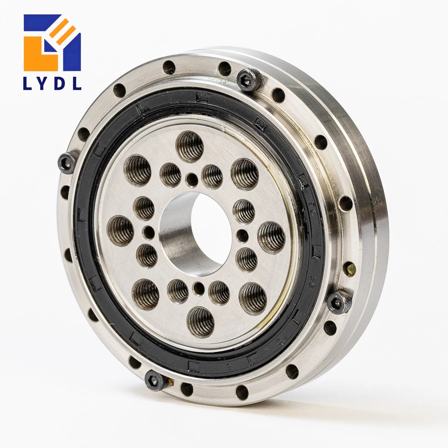
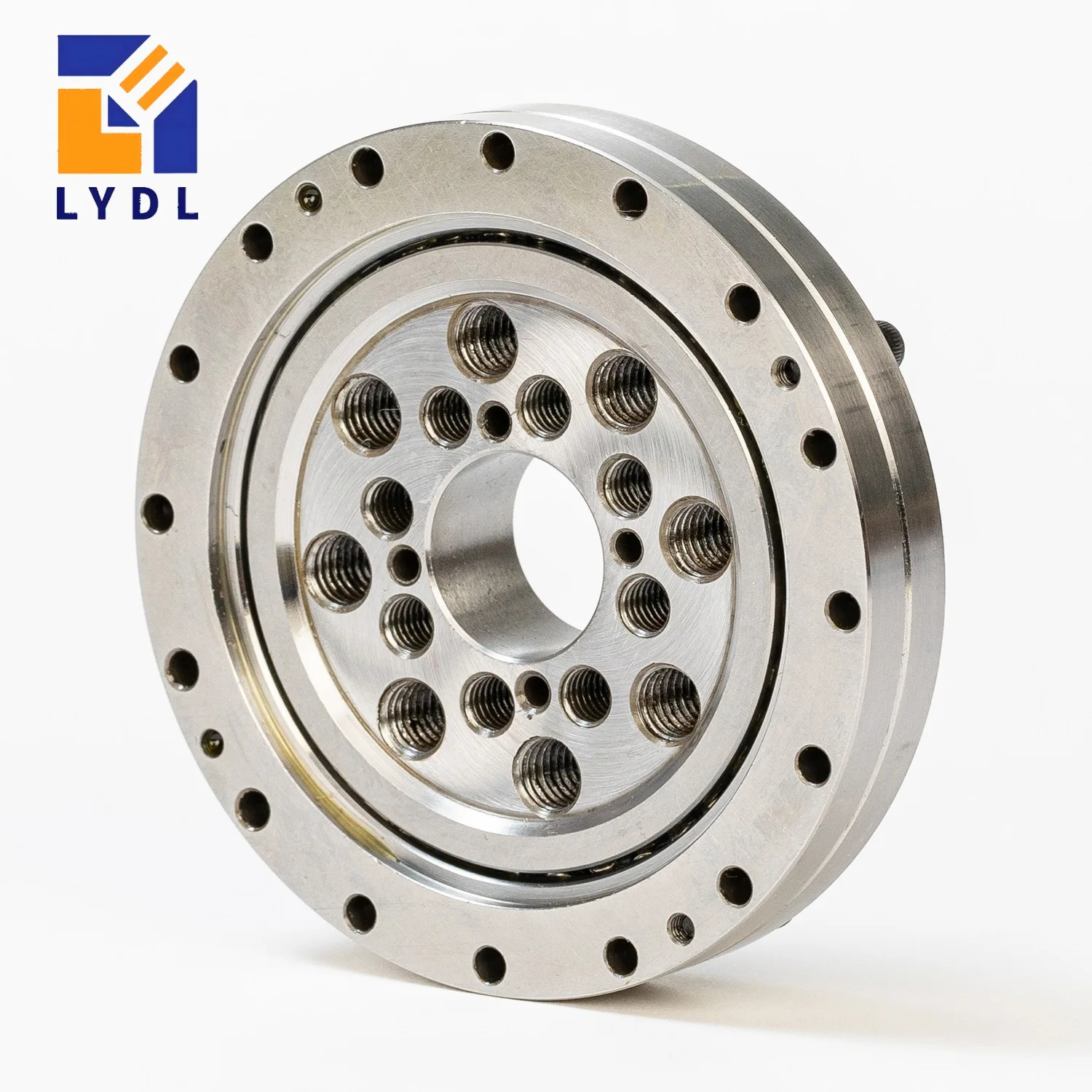
CSG-32 / CSF-32 cross roller bearing dimensions in the LYDL reference are 26 mm bore, 112 mm outside diameter and 22.5 mm overall height. For an articulated joint, the useful selection question is how its output support behaves throughout the load cycle. This page connects the dimensional interfaces to flange stiffness, moving payloads and an inspection plan for the assembled mechanism.
Compare this model with the CSG / CSF selection guide before confirming the interface.
A joint's load direction changes as the mechanism moves. Begin with a sketch showing the attached link, payload and working tool at the relevant positions. Record the centre-of-gravity distance, force directions and acceleration history. Include any contact or emergency stopping event that must be considered by the design engineer. The demanding bearing condition may occur away from the position with the greatest transmitted drive torque.
For a redesign, distinguish the existing support specification from the new task. A heavier tool, revised link or different motion profile can alter the requirement while the reducer size remains unchanged. Do not treat a size increase as a substitute for checking the assembly. The review needs a defined load path and the supplied bearing's confirmed performance, alongside the original family reference.
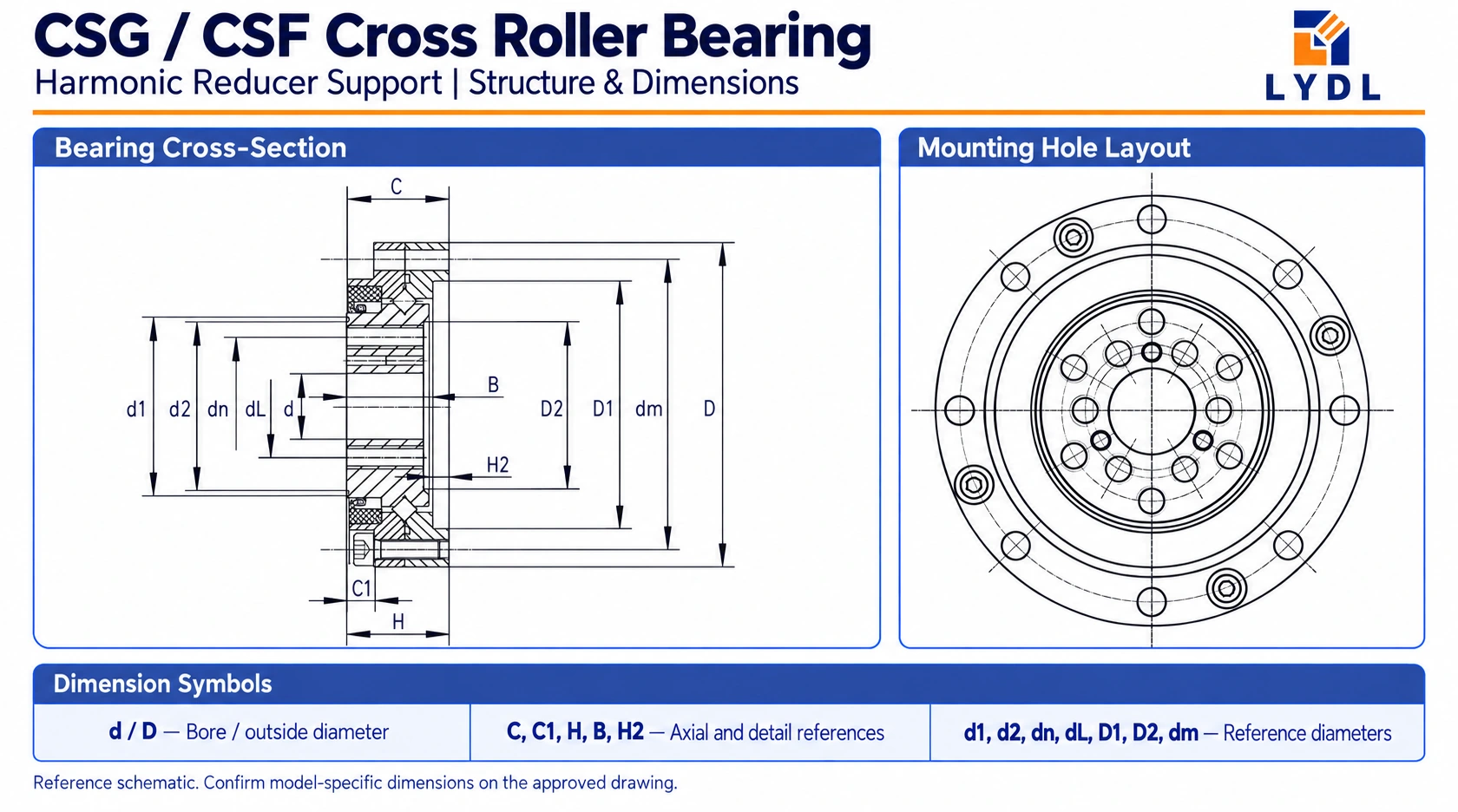
The section labels H, C, B and H2 describe the axial arrangement: the reference values are 22.5, 21.5, 19 and 3 mm respectively. d and D identify the central and outer diameters. Secondary diameters D1 = 90 mm, D2 = 64 mm, d1 = 74 mm and d2 = 68.6 mm locate other features; determine their mating surfaces on the model-specific drawing.
The outer reference lists sixteen 4.5 mm holes at dm = 104 mm. Eight M10 holes appear at dn = 55 mm, and the additional reference lists eight M10 holes on dL = 40 mm. Equal thread sizes do not establish equal mechanical roles. Verify the intended connection for each circle. The CSG / CSF bearing category provides related sizes for comparison without replacing this interface check.
| Reference feature | Value |
|---|---|
| d (mm) | 26 |
| D (mm) | 112 |
| H (mm) | 22.5 |
| C (mm) | 21.5 |
| B (mm) | 19 |
| H2 (mm) | 3 |
| D1 (mm) | 90 |
| D2 (mm) | 64 |
| d1 (mm) | 74 |
| d2 (mm) | 68.6 |
| Outer PCD dm (mm) | 104 |
| Outer fixing holes | 16-Φ4.5 |
| Inner PCD dn (mm) | 55 |
| Inner fixing holes | 8-M10 |
| Additional PCD dL (mm) | 40 |
| Additional fixing holes | 8-M10 |
Dimensions: existing LYDL selection reference. The approved model drawing defines tolerances, variant mapping and supplied interfaces.
Bearing support, housing stiffness, flange thickness and fastener behaviour all affect an articulated link. Describe the allowable movement where it matters to the process, not only at a convenient measurement surface. A working point far from the bearing can make small angular movement more noticeable. State the applied force and its position when requesting a loaded measurement or engineering assessment.
Do not copy a complete reducer's torsional stiffness into a standalone bearing attribute. Torsion about the driven axis and tilting under an external moment address different behaviour. Separate those requirements in the enquiry. When another construction could improve the available support geometry, compare the LYDL cross roller bearing range with the housing designer rather than relying solely on a family size designation.
The original 2UH table provides dynamic, static and moment reference values for its specified output-bearing assembly. Their numerical identity is retained below instead of combining them with different values from an earlier LYDL table. Reference C and C0 are load ratings, while section C is an axial dimension. Confirm the units and the relevant catalogue conditions before using any calculation.
For the actual joint, review combined force directions, moment arms and the time spent in each load state. Add acceleration and severe events as required by the machine design. Bearing life and maximum-load checks answer different questions. Obtain the supplied component's confirmed data and mounting assumptions; an original assembly comparison is useful context, but it is not a performance certificate for the replacement.
| Reference feature | Value |
|---|---|
| Basic dynamic load C (kN) | 15 |
| Basic static load C0 (kN) | 25 |
| Catalogue moment Mc (Nm) | 313 |
Harmonic Drive catalogue, printed page 33, Table 30. Source load units ×10² N converted to kN. Confirm configuration and rated conditions before calculation.
Measure the housing and link interfaces against the approved drawing. Look for surface damage, particles, uneven contact and hardware that might interfere during movement. Use the correct locating features rather than expecting clearance holes to centre the bearing. Apply the specified installation procedure and inspect rotation after each relevant part is secured.
Define mounted runout and running-torque checks with the load, temperature and measurement location. Record the clearance or preload configuration agreed for supply. A result from an unclamped bearing is not automatically the result of the finished joint. If the measured condition changes after assembly, examine the seats, flange contact and fastening before adjusting the component specification.
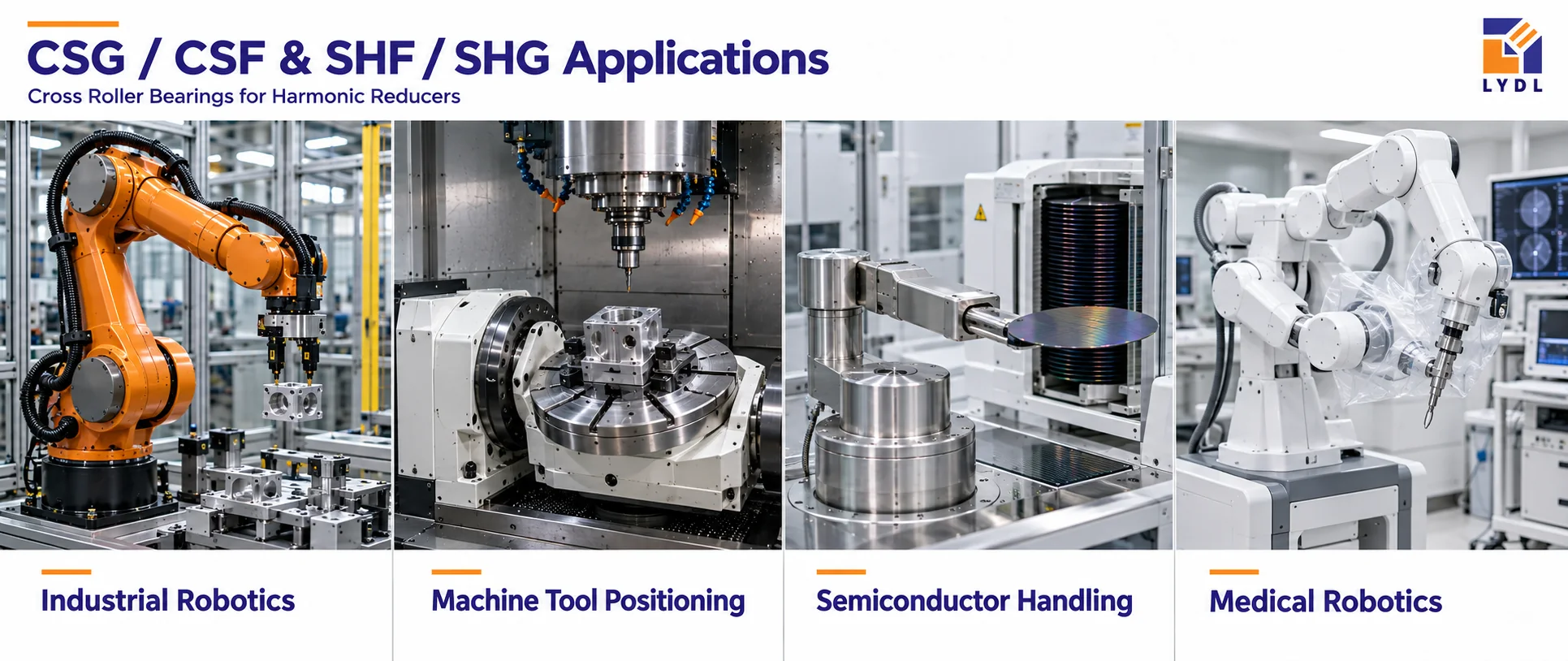
Industrial robotics can use comparable output support in an articulated joint carrying a link or wrist. Machine-tool positioning may place it behind an orienting mechanism whose process forces are defined. Semiconductor equipment can use articulated transfer axes where motion behaviour and environmental constraints both need review. Medical robotics may use a driven positioning joint with independent device-level validation.
The four-field image is a visual explanation of possible contexts. It is not proof of this model's fit or qualification in those applications. Required sealing, lubricant compatibility, materials and inspection conditions should be specified for the actual mechanism rather than inferred from the equipment name.
The inspection scope should identify the features controlling the joint: seats, flange steps, mounting circles, threads and agreed rotational characteristics. State how the supplied part and revision will be recognised on the report. If a loaded assembly test is needed, distinguish it from standard component inspection and agree its method. Consult LYDL company and manufacturing information for company information during the supplier assessment.
Specify protected mating faces and individual restraint for transport. Keep marking and handling instructions clear enough for maintenance staff to identify the correct replacement. The inspection image belongs alongside the agreed quality scope; representative packaging does not establish an unlisted test or acceptance limit.

The force direction and lever arm relative to the bearing change during articulation. Identify demanding positions and motion events rather than checking only the parked joint. Include the supported link, payload and working tool in the load description.
The table lists distinct dn and dL interfaces. Their mating parts and fastening functions must be identified on the drawing. Equal thread sizes do not make the circles interchangeable or confirm equivalent access and engagement.
These are different response measurements. Torsional stiffness concerns rotation about the drive axis; flange tilt can result from an external overturning load. Define the required behaviour, force location and measurement method for the assembled joint.
Record the bearing condition before mounting and repeat agreed measurements after clamping. Use consistent locations and test conditions. Inspect seat flatness, contact and bolt interference when assembly changes the observed rotation or runout.
Provide link geometry, payload location, force directions and the output motion profile. Identify severe stopping or contact events and the desired service life. Include the housing and flange drawings so performance can be assessed with the mounting arrangement.
Submit the size-32 joint drawings and load-position sketches through LYDL technical enquiry. Add the exact reducer configuration, acceptance method and required quantity. This allows LYDL to review the interfaces and proposed inspection scope as part of one component specification.
LYDL supplies its own bearings. Referenced brand names identify comparison families; agreed drawings and order specifications define supplied performance.