

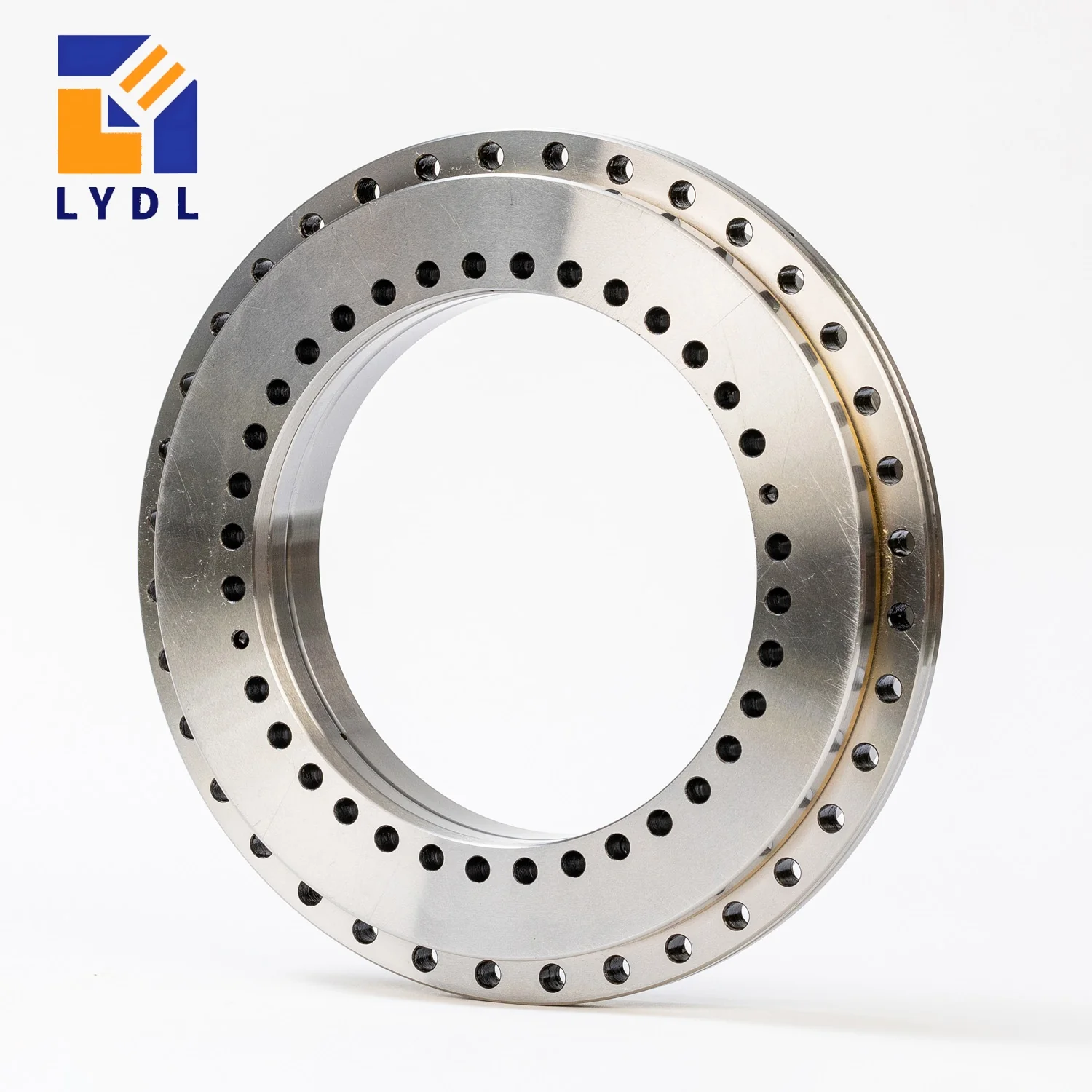
The ZKLDF200 rotary table bearing is LYDL’s 200 mm bore size in the double-row angular-contact ball family. Its outside diameter is 300 mm and its overall height is 45 mm. This envelope can be considered when laying out a hollow rotary axis with a torque motor, workholding flange and angular feedback system. The bearing contributes mechanical support; motor control, encoder arrangement and machine structure must be designed alongside it.
The source for the model dimensions is the LYDL ZKLDF series guide. Confirm the supplied bearing against an approved drawing, especially when an existing motor flange or table casting determines the installation interfaces.
| Parameter | Symbol | Value | Unit |
|---|---|---|---|
| Bore diameter | d | 200 | mm |
| Outside diameter | D | 300 | mm |
| Overall height | H | 45 | mm |
| Ring profile reference | H1 | 30 | mm |
| Inner fixing pitch circle | J | 215 | mm |
| Outer fixing pitch circle | J1 | 285 | mm |
| Inner fixing holes | nI × d1 | 46 × Ø7 | quantity × mm |
| Outer fixing holes | nA × d3 | 45 × Ø7 | quantity × mm |
| Inner counterbore diameter | d2 | 11 | mm |
| Counterbore depth | a | 6.2 | mm |
| Extraction thread reference | G | M8 | metric |
| Extraction positions | — | 3 | quantity |
| Retaining screw reference | — | 2 | quantity |
| Published mass reference | m | 11 | kg |
Dimensions and mass: LYDL series table. Symbols follow its structure diagram. Mass is a reference; drawing approval defines the supplied unit. Load ratings, limiting speed, preload and numerical tolerances require configuration-specific confirmation.
With 200 and 300 mm boundary diameters, the nominal radial section is 50 mm. This is a layout calculation rather than a shoulder specification. Locate the actual support areas using the ring profile, and show any motor-centering features independently. A motor pilot and a bearing seat may share an axis but do not automatically share their tolerance or contact requirements.
The 30 mm H1 value refers to the profile shown in the series drawing. Keep it distinct from the 45 mm total height when arranging the rotating flange and stationary cover. Add the axial positions of the encoder scale, protective seals and service connections to the same stack so their assembly sequence is visible before manufacture.
ZKLDF200 uses the listed 215 mm inner-ring fixing pitch circle and 285 mm outer-ring fixing pitch circle. The associated fixing quantities are 46 and 45. The inner counterbore is listed at 11 mm diameter with 6.2 mm depth. Confirm all features against the drawing, including the angle from the machine datum to the first relevant position.
A direct-drive layout often places competing components near those fastening circles. Check whether the motor stator, coolant jacket or encoder bracket obstructs the screw tool. Include service access for future removal. An extraction thread should remain accessible and correctly identified; it should not accidentally become a mounting location for a cable clamp or protective cover.
Review the stiffness of the rotating table plate and the stationary bearing carrier. A rigid-looking motor assembly can still distort the bearing if screws act through an uneven support face. Plan a controlled tightening sequence and measure the fitted assembly before and after installing other large clamped components. This makes it easier to isolate the source of a changing runout or turning-torque reading.
| Model | Bore d | Outside D | Height H |
|---|---|---|---|
| ZKLDF150 | 150 | 240 | 40 |
| ZKLDF200 | 200 | 300 | 45 |
| ZKLDF260 | 260 | 385 | 55 |
Relative to ZKLDF150, the 200 size adds 50 mm to the bore, 60 mm to the outside diameter and 5 mm to the overall height. Moving onward to ZKLDF260 adds another 60 mm of bore and 85 mm of outside diameter. Those are substantial changes to motor packaging and the supporting housing, so compare a complete axis layout rather than a bearing alone.
The YRT200 model uses the same nominal 200 × 300 × 45 mm boundary size with a different rolling arrangement. The YRT, YRTS and YRTM guide helps distinguish mechanical support from higher-speed family selection and angular measurement. A ZKLDF designation does not itself include a motor, drive controller or encoder. Define those functions explicitly in the machine specification.
For a direct-drive table, consider a workholding plate attached to the rotating bearing side and a stationary carrier connected to the machine structure. The candidate duty can combine workpiece weight, process loads and repeated acceleration. Workpiece offset converts some forces into overturning moment, while moving inertia determines the acceleration torque demanded from the motor.
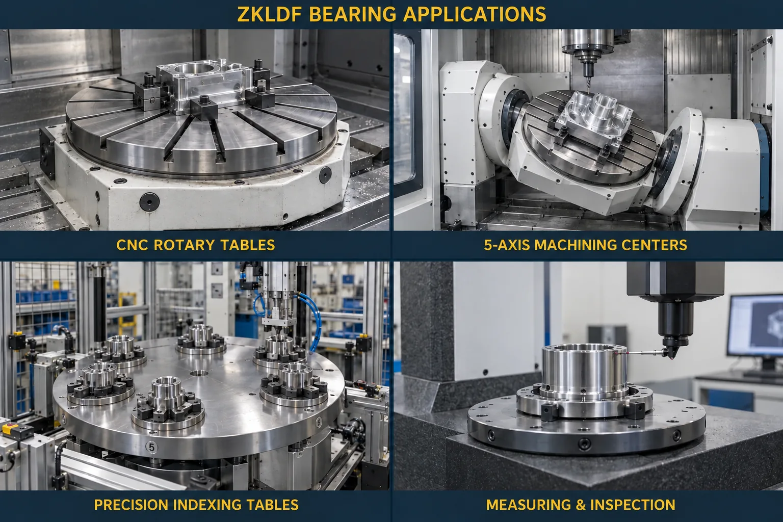
Calculate those effects using the installed table, chuck, fixture and part. Bearing size does not establish the inertia of the completed axis, and bearing load capacity does not establish motor torque. Prepare separate mechanical-load and drive-torque cases, then bring them together in the thermal and motion review. The series application image illustrates possible equipment contexts rather than a validated ZKLDF200 installation.
A torque motor can introduce a temperature gradient between the inner and outer structures. Show the cooling arrangement, expected duty and temperature monitoring points when discussing the bearing. The relevant issue is the condition at the bearing position over the operating cycle, not only the motor’s catalogue temperature or the room temperature at start-up.
Document time at speed, acceleration ramps, dwell and reversal frequency. Ask LYDL to confirm lubrication, preload-related requirements and permitted operation for that configuration. Values from a different branded ZKLDF catalogue must not be treated as guaranteed LYDL limits. When an axis behaves differently during warm-up, compare temperature and torque trends with the same mechanical arrangement and control settings. Note the coolant condition and the timing of each measurement, so readings from different operating stages are not treated as directly equivalent.
State the requested precision level, such as P5, P4 or P2, and identify the numerical features required by the machine. Bearing running accuracy and encoder resolution are separate quantities. Their effect at the tool or workpiece also depends on structural alignment, loading and the distance from the measurement point to the axis.
For the ZKLDF200 order, specify identification, nominal interfaces and the agreed inspection record. If fitted torque or runout is part of acceptance, define whether the reading concerns the bearing component or the customer’s complete axis. Those results should not be compared without understanding the different clamping and temperature conditions.
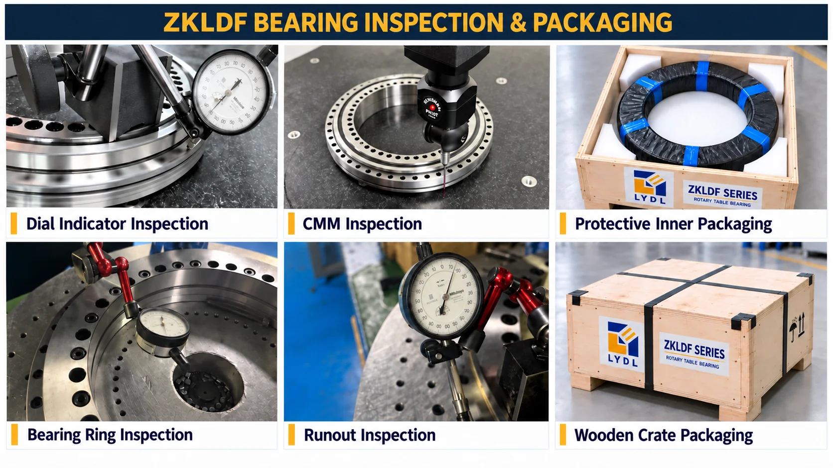
The common inspection-and-packaging graphic is illustrative. Agree the actual preservation method and package with the shipment requirements. Keep finished faces protected from particles during unpacking and prevent the package from transferring impact through a narrow unsupported point. Check the model marking and documentation before committing the assembly to the motor carrier.
The designation identifies the mechanical bearing in this listing. Specify the encoder or other measuring system separately. Check its mounting space, datum relationship and interface with the intended controller during the complete axis review.
No. Motor torque, rotor geometry, cooling, inertia and mounting details require their own selection. The 200 mm bore is one boundary dimension, not a statement that an arbitrary motor or rotary union will fit.
The nominal inner and outer fixing pitch circles are 215 and 285 mm. The LYDL table lists forty-six inner and forty-five outer fixing holes. Verify angular references and auxiliary features before releasing the flange drilling.
They share the quoted principal envelope, but their rolling construction and operating behaviour differ. Check every interface plus stiffness, lubrication, preload, precision and the application load cycle before considering an exchange.
Include the motor cooling concept, time at operating speed, ambient range and known temperatures near both ring supports. Supply the axis section so heat sources and the path into the bearing position can be reviewed together.
Ask LYDL to review the bearing position with your load diagram, speed cycle and motor layout. The main rotary bearing category links the available families. TPI 120 from Schaeffler provides independent architecture terminology; supplied performance remains subject to the LYDL technical agreement.
Email: sales@luoyangdeeplink.com. Browse the ZKLDF product category for published family entries.