

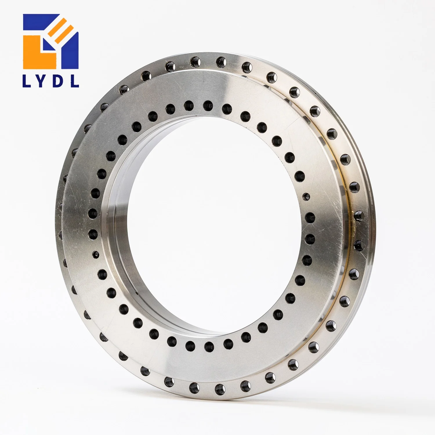
LYDL lists the ZKLDF150 rotary table bearing at 150 × 240 × 40 mm. Its double-row angular-contact ball construction provides a compact bearing position for a rotary assembly subject to axial forces, radial forces and overturning moment. The 150 mm bore creates room for a hollow spindle or central services, while the 40 mm overall height keeps the nominal axial envelope equal to ZKLDF120. The fastening interface, however, changes substantially between those sizes.
Use the complete ZKLDF selection table to identify this model within the range. The following numbers are published LYDL reference dimensions. Final ring profiles, ordered precision and operating conditions belong on the accepted supply drawing.
| Parameter | Symbol | Value | Unit |
|---|---|---|---|
| Bore diameter | d | 150 | mm |
| Outside diameter | D | 240 | mm |
| Overall height | H | 40 | mm |
| Ring profile reference | H1 | 26 | mm |
| Inner fixing pitch circle | J | 165 | mm |
| Outer fixing pitch circle | J1 | 225 | mm |
| Inner fixing holes | nI × d1 | 34 × Ø7 | quantity × mm |
| Outer fixing holes | nA × d3 | 33 × Ø7 | quantity × mm |
| Inner counterbore diameter | d2 | 11 | mm |
| Counterbore depth | a | 6.2 | mm |
| Extraction thread reference | G | M8 | metric |
| Extraction positions | — | 3 | quantity |
| Retaining screw reference | — | 2 | quantity |
| Published mass reference | m | 7.5 | kg |
Dimensions and mass: LYDL series table. Symbols follow its structure diagram. Mass is a reference; drawing approval defines the supplied unit. Load ratings, limiting speed, preload and numerical tolerances require configuration-specific confirmation.
The difference between outside and bore diameters is 90 mm, giving a nominal 45 mm radial section on either side. That is the same boundary-section calculation as for ZKLDF120, although the two assemblies have different diameters and fixing arrangements. It should not be mistaken for a constant usable shoulder width or proof that their mounting stiffness is equal.
Place the 26 mm H1 feature in the correct axial section before designing an adjacent cover. The model’s complete height remains 40 mm. A drawing that assigns 26 mm to the overall stack can shift the fixture datum and foul the stationary structure. Include the external seal, labyrinth or cover attachment separately; those parts do not disappear because the bearing itself is compact.
The listed fixing pattern has 34 inner-ring and 33 outer-ring holes. Their pitch circles are 165 and 225 mm. This differentiates ZKLDF150 from the 22/21-hole ZKLDF120 even though their nominal height and hole diameters match. Reusing a smaller adapter therefore requires a fresh interface design, not merely a new centre opening.
Bring the machine datum, angular origin and bearing-hole identification into the adapter drawing. Where a workholding plate has multiple independent patterns, mark which fasteners clamp the bearing and which attach the fixture. Avoid letting an accessory bolt bottom against the bearing ring or obstruct an extraction feature. Confirm screw length using the complete stack and the mating thread depth.
An inspection fixture may have a stiff outer base but a relatively thin rotating plate. Assess both sides of the bearing. Uneven clamping or local plate bending can introduce fitted runout that is absent in the component’s inspection record. Measure after the intended screw sequence and again after attaching the final workholding tooling, recording the measurement radius and load state. Mark the fixture orientation in that record so a later reassembly can reproduce the same reference position.
| Model | Bore d | Outside D | Height H |
|---|---|---|---|
| ZKLDF120 | 120 | 210 | 40 |
| ZKLDF150 | 150 | 240 | 40 |
| ZKLDF200 | 200 | 300 | 45 |
ZKLDF120 offers a smaller 120 mm bore and 210 mm outside diameter at the same listed height. ZKLDF200 moves to 200 × 300 × 45 mm, adding both radial and axial space requirements. Choosing between them should begin with the fixture layout and load diagram, followed by the capacity and deflection calculation for the actual rotating assembly.
The YRT150 bearing page supplies a roller-bearing comparison with the same basic envelope. A designer may compare the two concepts when deciding how the axis balances rotational behaviour and support stiffness. Consult the YRT family selection guide for the roller architecture and available family variants. Neither matching dimensions nor a similar model number establishes equivalent supplied performance.
A candidate application is a turntable carrying a component that must be measured from several angular positions. The ZKLDF150 bearing supports the mechanical axis while an independent measurement system establishes angle. If the part is offset from the centre, its weight creates a tilting moment through the horizontal distance to the bearing axis.
In the review, distinguish the fixture’s own eccentricity from the bearing’s radial motion. A reference surface on the fixture can help establish whether a reading changes because of workholding, assembly or spindle motion. Specify where that surface is measured and how the part is clamped. This approach gives an actionable acceptance method instead of attributing every observed error to the bearing grade.
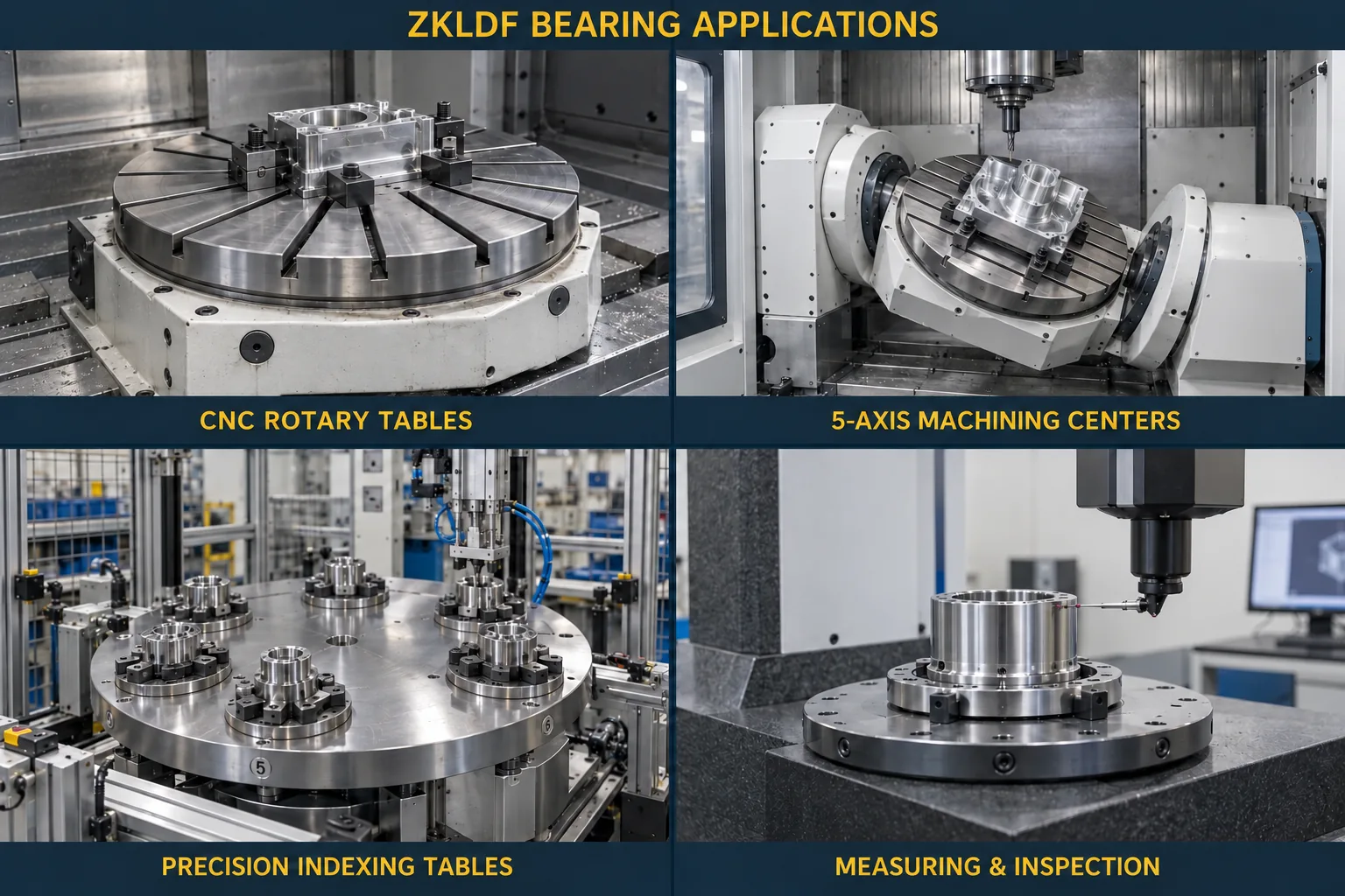
List the maximum part mass, centre-of-gravity offset and any contact force applied by a gauge or process tool. Include loading and unloading states as well as the normal measuring state. A fixture may experience its largest unbalanced moment while an operator or robot places the part, even when the measurement cycle itself applies little force.
State whether the axis rotates continuously, indexes between stops or reverses through a limited arc. The appropriate lubrication and permitted speed depend on that duty and the supplied configuration. Do not interpret the series description as a guarantee of an arbitrary spindle speed. For an enquiry, identify the requested P5, P4 or P2 precision and the fitted-axis accuracy target separately.
Position cable loops and rotary services so they do not impose a changing external torque during measurement. When a measurement is sensitive to settling, observe the complete drive-and-fixture response after an index move. Bearing dimensions alone cannot establish that settling time, and an application illustration cannot demonstrate it for the proposed machine.
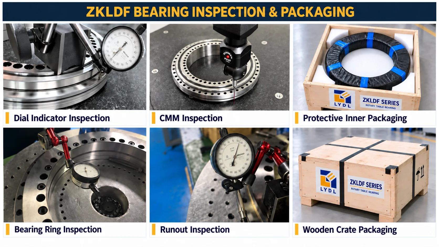
Agree the ZKLDF150 checks before the order is released: identification, boundary dimensions, fixing interfaces and specified running accuracy. If both rings have acceptance datums, state the support and clamping conditions used during inspection. The delivered report should be interpretable against the customer’s assembly drawing, rather than consisting of unexplained readings.
For shipment, choose protection that keeps finished surfaces isolated from hard loose items and moisture exposure. The illustration depicts generic inspection and case-packing methods. The actual package and any inspection documentation are order-specific. Retain the protective support until the bearing reaches a prepared assembly area, and verify the item marking before fitting it into the fixture.
ZKLDF150 provides a 150 mm bore and 240 mm outside diameter while retaining a nominal 40 mm height. That can resolve a central-passage constraint, but it requires different seats, bolt circles and fastening quantities.
No. The published inner-ring quantity is thirty-four and the outer-ring quantity is thirty-three. Confirm the angular layout and any auxiliary positions using the complete model drawing before machining the adapter.
Establish the moving mass and its centre-of-gravity offset, then determine the resulting forces and moments for each orientation. Include the fixture, component, services and loading sequence in the review rather than considering part mass alone.
The photograph is a series reference reused with a separate media attachment for this listing. Exact steps, drilling details and delivered configuration are defined by the accepted ZKLDF150 drawing, not by counting features in that image.
Separate component running accuracy from fixture and machine requirements. State the measurement datum, radius, clamping condition and temperature, then agree which bearing records and fitted-axis tests are necessary for the project.
Provide the fixture section, workpiece offsets and rotation sequence through Contact LYDL. Return to the rotary table bearing range to compare the families. Schaeffler’s technical publication is a structural reference; the LYDL order drawing and agreed inspection criteria govern the supplied item.
Email: sales@luoyangdeeplink.com. Browse the ZKLDF product category for published family entries.