

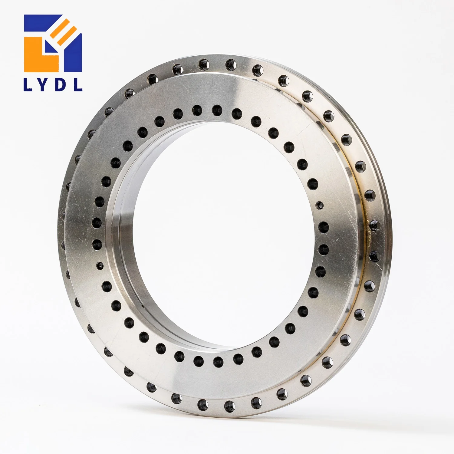
A ZKLDF120 rotary table bearing from LYDL combines a 120 mm bore with a 210 mm outside diameter and 40 mm overall height. The two angular-contact ball rows provide the series architecture for supporting axial and radial forces together with a tilting moment. This size is a useful starting point when the 100 mm opening of ZKLDF100 constrains services, yet the designer wants to avoid the larger 240 mm outside envelope of ZKLDF150.
The ZKLDF model selection page supplies the nominal data used below. Treat those figures as the published layout reference and release manufacturing interfaces against the agreed LYDL drawing, including the ordered accuracy and lubrication arrangement.
| Parameter | Symbol | Value | Unit |
|---|---|---|---|
| Bore diameter | d | 120 | mm |
| Outside diameter | D | 210 | mm |
| Overall height | H | 40 | mm |
| Ring profile reference | H1 | 26 | mm |
| Inner fixing pitch circle | J | 135 | mm |
| Outer fixing pitch circle | J1 | 195 | mm |
| Inner fixing holes | nI × d1 | 22 × Ø7 | quantity × mm |
| Outer fixing holes | nA × d3 | 21 × Ø7 | quantity × mm |
| Inner counterbore diameter | d2 | 11 | mm |
| Counterbore depth | a | 6.2 | mm |
| Extraction thread reference | G | M8 | metric |
| Extraction positions | — | 3 | quantity |
| Retaining screw reference | — | 2 | quantity |
| Published mass reference | m | 6 | kg |
Dimensions and mass: LYDL series table. Symbols follow its structure diagram. Mass is a reference; drawing approval defines the supplied unit. Load ratings, limiting speed, preload and numerical tolerances require configuration-specific confirmation.
Both a rotating spindle and a stationary support may occupy the area around a hollow axis. On a 210 mm bearing, the surrounding machine still needs material for its outer seat, fastening threads, cover location and any environmental protection. Therefore, 210 mm describes the bearing diameter rather than the required external diameter of the completed housing.
The nominal radial section is 45 mm, obtained from the difference between D and d divided by two. The calculation describes the boundary geometry only. It does not identify an allowable shoulder width, because the ring profiles and bolt recesses interrupt that space. Similarly, H1 at 26 mm is a profile reference, not an alternative overall height. Use the full 40 mm height when checking the nominal bearing stack and then add the surrounding components.
For this model, the fixing layout uses 22 inner-ring holes on a 135 mm pitch circle and 21 outer-ring holes on a 195 mm pitch circle. These are not the hole quantities used by either neighbouring model. A machining program inherited from another size should be reviewed from its datum definition, rather than edited only by scaling the circle diameter.
In particular, distinguish a pitch arrangement from the number of occupied fixing positions. Retaining and extraction features have separate purposes. Obtain the angular origin and feature identification from the complete drawing before drilling an adapter. The inner recess information, 11 mm diameter and 6.2 mm depth, should be checked with the proposed fastener head and access tool.
The supporting flanges influence how the bolted rings behave. Examine discontinuities such as a cable window, a thin motor flange or a large pocket behind one segment of the seat. If a support section is interrupted, evaluate its deflection instead of assuming that the nominal ring accuracy will persist after clamping. Record any fitted-state runout measurement at a defined radius and assembly temperature.
| Model | Bore d | Outside D | Height H |
|---|---|---|---|
| ZKLDF100 | 100 | 185 | 38 |
| ZKLDF120 | 120 | 210 | 40 |
| ZKLDF150 | 150 | 240 | 40 |
Compared with ZKLDF100, the centre opening increases by 20 mm and the outside diameter by 25 mm. Compared with ZKLDF150, this bearing keeps the same nominal 40 mm height but uses a bore 30 mm smaller and an outside diameter 30 mm smaller. Those relationships are helpful when a rotary union and a housing diameter compete for space.
Use the YRT120 technical page to compare a roller-based support occupying the same principal dimensions. Evaluate the contact arrangement, fitted stiffness and friction requirements as well as the complete fixing pattern. Broader distinctions appear in the YRT / YRTS / YRTM selection reference. A common boundary size by itself is insufficient evidence of interchangeability.
A potential ZKLDF120 installation is a measuring turntable that rotates a fixture while a probe or optical sensor observes the part. The 120 mm central opening may accommodate an inner column or services, subject to the assembled passage. The bearing’s task is to support the table; the measurement result also depends on the fixture datum, probe geometry and machine calibration.
Plan how the instrument distinguishes spindle motion from workpiece error. Measure a suitable reference artefact and record the configuration in which it is supported. Reversing the part or changing its radial location can help the engineering team identify error contributors, but the procedure must be defined for the particular measuring system. No unverified accuracy figure is implied by this application example.
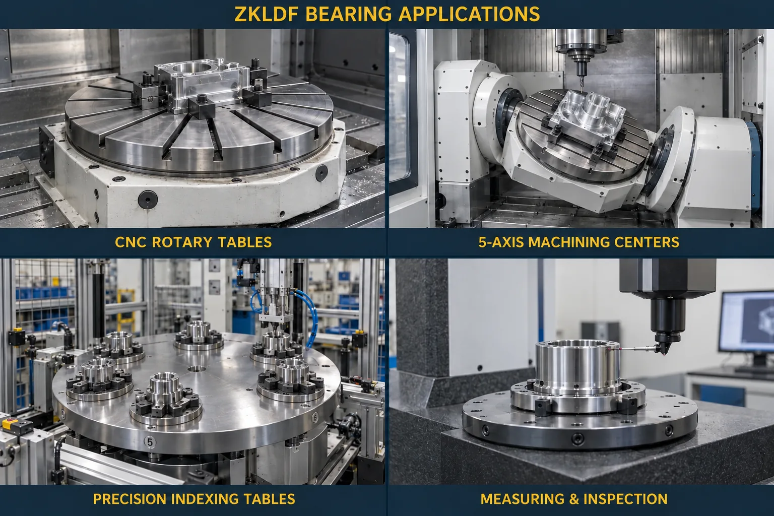
Inspection equipment may spend long periods close to standstill and then execute short angular moves. Include that behaviour in the operating description. A maximum rotational speed says little about reversal frequency, lubricant distribution at small movements or the settling time needed before a measurement. These conditions belong in the bearing and drive review together.
Keep motor heat, ambient changes and the position of the temperature sensor visible in the test plan. A reading taken immediately after assembly should not be compared casually with one taken after an extended production cycle. Define a repeatable warm-up and measurement sequence for the complete axis, and specify the permitted change at the point where the workpiece is measured.
Precision requirements should identify the relevant running surfaces and datums. LYDL enquiries can state P5, P4 or P2 as the requested grade, with final numerical acceptance agreed for the supplied bearing. A smaller grade number does not compensate for an incorrectly located encoder or an insufficiently stable mounting plate.
Ask for the ZKLDF120 designation, nominal dimensions and ordered accuracy features to be traceable to the same item. If inspection results are needed for the machine dossier, define which results are recorded and how the bearing is supported during measurement. This avoids receiving a document that uses a different datum from the machine’s acceptance procedure.
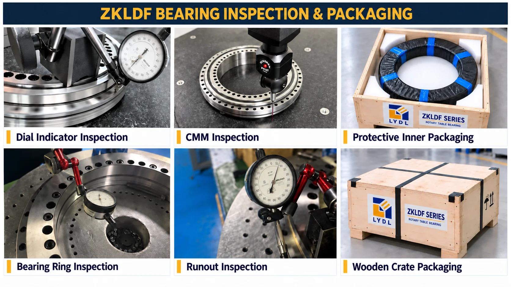
The common packaging illustration describes protective handling concepts. Confirm the actual protective wrapping and shipping container with the order. Preserve covers until the clean installation area is ready, and prevent abrasive packing debris from reaching the mounting surfaces. On receipt, check the package for movement damage before removing the bearing from its support.
No. The 120 size changes the bore, outside diameter, height, bolt circles and fixing-hole quantities. Its envelope is 120 × 210 × 40 mm, so the complete mounting arrangement needs its own drawing review.
The published LYDL data identify twenty-two inner-ring and twenty-one outer-ring fixing holes. Check their angular locations, auxiliary features and access clearances on the released drawing rather than deriving them from a photograph.
Both are listed with 40 mm overall height. ZKLDF150 enlarges the bore and outside diameter to 150 and 240 mm. Ring profiles and fixing details still differ, so equal height does not establish a common installation.
Describe the angular travel, number of reversals, dwell duration and time allowed before readings. The review should address lubricant behaviour, drive disturbances and the complete measuring setup, in addition to nominal bearing dimensions.
A grade helps specify the component, but the machine needs an explicit test method. Identify the datum, measurement radius, temperature condition and assembled load so the bearing inspection and table acceptance criteria can be compared meaningfully.
Send your mounting section and operating sequence by emailing LYDL. Include any maximum housing diameter and usable bore requirement. Browse the rotary table bearing catalogue for the surrounding family. The Schaeffler structural reference explains the bearing concept; its branded ratings do not define LYDL supply performance.
Email: sales@luoyangdeeplink.com. Browse the ZKLDF product category for published family entries.