

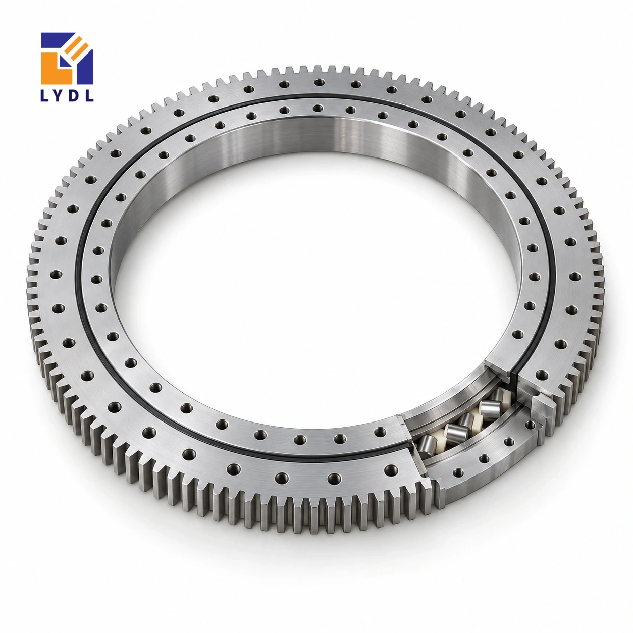
XA160596 is a LYDL external gear cross roller listing with a 510 mm bore, 712.3 mm outside diameter and 55 mm overall height. Its transmission entry gives module 6, 117 teeth and a 702 mm pitch diameter.
XA160596: nominal LYDL listing. INA interchange unverified. Supplied execution requires an agreed drawing.
XA specification tables · Family technical reference
| Bore (mm) | Outside (mm) | Height H (mm) | Mass ≈ (kg) |
|---|---|---|---|
| 510 | 712.3 | 55 | 63 |
| Outer PCD La (mm) | Inner PCD Li (mm) | Outer holes na | Hole dB (mm) | Secondary h (mm) |
|---|---|---|---|---|
| 650 | 542 | 24 | 18 | 48 |
| Pitch d0 (mm) | Module m (mm) | Teeth z | Width b (mm) |
|---|---|---|---|
| 702 | 6 | 117 | 48 |
The 712.3 mm outside envelope is close to the 708 mm listing of XA260560, but their bores, heights and gears differ substantially. XA160596 has module 6 with 117 teeth; XA260560 lists module 10 with 69 teeth. A housing-size comparison cannot determine whether the same pinion or drive bracket can be reused. Review the axial engagement, mounting datums and load requirements before narrowing the choice.
Twenty-four outer positions are listed on a 650 mm circle with 18 mm holes, while the inner fixing circle is 542 mm. Place the complete fastening arrangement alongside the external drive in the assembly model.
Check maximum width with the external motor and guard in their largest adjustment positions. A bearing that fits inside the base frame can still produce an oversized machine once the pinion support is added. Include cable connectors and the path needed to remove the motor; servicing clearance may extend beyond the operating envelope. Compare alternative layouts using the same equipment requirements rather than using close ring outside diameters as the main selection criterion.
The near-sized XA260560 has a different module, tooth count and bore, so it represents a distinct transmission and flange proposal. Define which machine dimensions are fixed and which can be redesigned. Provide the load carried at maximum reach and state whether the platform accelerates in that configuration. Include side forces introduced by guides, grippers or product transfer.
Where a structure is constrained by width, its local flange section and bracket attachment deserve explicit review. Do not omit those details because the frame looks substantial overall. Ask for the offered LYDL drawing with the selected gear execution and establish the inspection features relevant to that arrangement. A clear constraint-based enquiry is more useful than a request for any bearing with approximately the same outside size.
The XA160596 gear row describes external teeth with module 6 and 117 teeth. Their product is 702 mm, matching the listed nominal pitch diameter. That arithmetic checks the relationship between three entries; it does not calculate a permissible tooth force. The physical outside diameter is 712.3 mm and the bore is 510 mm, so neither should be replaced by the pitch-circle value in a clearance drawing. Overall height H is 55 mm. Locate the gear face and the two mounting planes from the offered section before positioning a pinion. The tooth form, engagement, quality requirement and supplied material execution remain separate specification items. Keeping these definitions distinct prevents a correct transmission number from being used as the wrong housing dimension.
The 510 mm bore may accommodate a stationary feature or process passage. Draw its real envelope together with the rotating fixture, including connectors and components that need occasional removal. At the perimeter, place the external pinion and its support beyond the 712.3 mm nominal bearing envelope. Review both operating motion and service access.
The listed 55 mm height is one element of the working stack. Include plates, adapters and locating shoulders when setting the platform level. A central passage can be adequate in diameter but impractical to assemble if fasteners become trapped beneath the installed fixture. Determine the installation sequence before committing to the final ring orientation.
Show the workpiece and tooling at their actual radii, including an entering or departing part. Edge guides, clamps and stops can introduce forces that differ from the weight carried during rotation. State their directions and heights. Identify permitted partial occupancy instead of assuming the table is always symmetrically loaded.
For the moving phases, describe angular travel, acceleration, stopping and the mass distribution. Define the desired installed behaviour at a working datum. The support plate, joints and drive all contribute to that observation. A crossed-roller family designation does not assign a numerical platform stiffness, and the approximate 63 kg ring mass does not establish a handling capacity for the finished table.
The gear uses nominal module 6 and 117 teeth, with a 702 mm pitch circle. The listed gear width is 48 mm, separate from the 55 mm total height. Use the offered section to establish pinion overlap and the relationship to the two seating planes. Specify the actual mating pinion when requesting transmission review.
There are twenty-four positions per ring on the 650 mm outer and 542 mm inner fixing circles. Check the supporting annuli against access pockets and the drive bracket. Include screw engagement, seats and locating details. Confirm how tools reach every connection with the guard and central equipment fitted. A complete interface review connects these nominal circles to a buildable station.
This extended XA row has not been independently established as a complete original-brand equivalent. Ask LYDL to identify the offered drawing and applicable execution. For a replacement, mark every existing interface that must be preserved and review any proposed change before machining.
Describe the dust, cleaning and idle environment when discussing protection and service access. Keep receiving records with the actual component identity and drawing revision. During commissioning, record the tooling and drive state for the baseline observation. If a guide, fixture overhang or motion schedule changes later, compare it with that accepted operating record rather than assuming the unchanged model number covers the revised duty.
XA140640 enlarges the opening from 510 to 571 mm and the outside envelope from 712.3 to 742.3 mm, while lowering nominal height from 55 to 50 mm. The common module 6 remains, but the ring tooth count changes from 117 to 122. Its forty-four-position connection also differs from the twenty-four positions here.
For the edge-loaded transfer table, keep the product locations fixed on the comparison drawings. Check whether the extra opening serves the central equipment or merely introduces a different flange. Include the changed pinion level and tooling access. The geometric comparison identifies redesign work; it does not establish a superior operating capacity or an approved replacement without the individual supply drawing.
If a transfer guide is repositioned, show its revised contact point and force direction. Review that change with the accepted fixture duty even where the workpiece mass and bearing identity remain unchanged.
A material-transfer table with restricted outer clearance is a representative case. Compare the drive projection and guard envelope, since these may govern machine width more than the bearing itself.

Specify the required locating and gear checks for the selected execution. Keep the external tooth perimeter protected from knocks when the ring is moved between receiving and assembly.

Do not assume so. Their listed modules are 6 and 10 respectively, with different tooth counts and pitch diameters.
LYDL lists 510 × 712.3 × 55 mm, with approximate bearing mass 63 kg.
The nominal outer circle is 650 mm with twenty-four listed positions; the inner circle is 542 mm.
The external pinion, motor support and guarding can project beyond the ring. Include their complete envelopes during layout.
Use the LYDL XA160596N row to initiate drawing review. It does not independently establish standard INA identity or a direct replacement guarantee.
Pinion inside: XI series. Standard external-gear group: XSA range.
Provide the maximum machine-width allowance and proposed pinion bracket when requesting XA160596.