

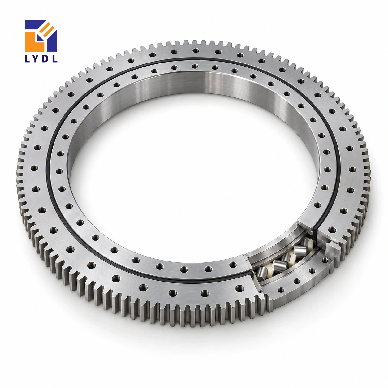
The XA160407 externally geared bearing is listed by LYDL with a 335 mm bore, 503.3 mm outside diameter and 50 mm total height. Its module 5 gear has 99 teeth and a 495 mm pitch diameter.
XA160407: nominal LYDL listing. INA interchange unverified. Supplied execution requires an agreed drawing.
XA specification tables · Family technical reference
| Bore (mm) | Outside (mm) | Height H (mm) | Mass ≈ (kg) |
|---|---|---|---|
| 335 | 503.3 | 50 | 33 |
| Outer PCD La (mm) | Inner PCD Li (mm) | Outer holes na | Hole dB (mm) | Secondary h (mm) |
|---|---|---|---|---|
| 455 | 359 | 30 | 13 | 45 |
| Pitch d0 (mm) | Module m (mm) | Teeth z | Width b (mm) |
|---|---|---|---|
| 495 | 5 | 99 | 45 |
XSA140414 also has a module 5, 99-tooth gear reference and the same listed outside diameter, but its bore, height and mounting interfaces differ. A shared tooth count may help compare drive concepts; it does not establish a complete bearing replacement. Overlay the locating shoulders and both fixing circles, then review the required running behaviour and supplied execution. Retaining an existing pinion also requires a detailed gear compatibility check.
The XA160407 row lists thirty outer positions on a 455 mm circle and a 359 mm inner circle, with 13 mm hole diameter. Check the actual inner pattern and screw-seat arrangement before reusing a flange.
Create a comparison sheet with a column for each bearing proposal and a row for every mating feature. Include the bore, locating shoulders, ring heights, fixing circles, angular hole positions and gear-face location. Mark genuinely matching features, unresolved details and features requiring an adapter. A common module and tooth count should occupy only part of that sheet.
If the existing pinion is to be retained, provide its drawing or measurement record and the intended acceptance requirement for the mesh. Check wear separately; a nominal geometric match does not establish the condition of a reused transmission. Define the outcome expected from the replacement. For example, a machine with lost movement during reversal needs an observation at the output, with the load and direction stated.
The cause may involve mesh clearance, supports, controls or the ring execution. Review the stationary fixture load at the same time as the indexing motion. A process tool can impose a reaction that is absent during rotation. This evidence helps LYDL assess an appropriate proposal and helps the equipment engineer decide which mating parts can remain.
The accepted supply drawing then becomes the basis for machining, rather than the catalogue photograph or a shared outside dimension.
The XA160407 gear row describes external teeth with module 5 and 99 teeth. Their product is 495 mm, matching the listed nominal pitch diameter. That arithmetic checks the relationship between three entries; it does not calculate a permissible tooth force. The physical outside diameter is 503.3 mm and the bore is 335 mm, so neither should be replaced by the pitch-circle value in a clearance drawing. Overall height H is 50 mm. Locate the gear face and the two mounting planes from the offered section before positioning a pinion. The tooth form, engagement, quality requirement and supplied material execution remain separate specification items. Keeping these definitions distinct prevents a correct transmission number from being used as the wrong housing dimension.
A rotary station may use the 335 mm opening for a fixed support, service route or process passage. Show that feature alongside the moving platform and external pinion. Establish which parts are stationary and which rotate; a clear bore alone does not describe the relative motion or the clearance needed by attached tooling.
At the perimeter, include the tooth envelope, pinion bracket and guarding. A machine footprint that accommodates the 503.3 mm bearing diameter may still be too small for the drive assembly. Check access to adjustment fasteners and the route for replacing the pinion. These details are easiest to settle while the basic support drawing can still be changed.
The module 5 gear has 99 listed teeth and a nominal pitch diameter of 495 mm. A different XA model with the same module does not automatically preserve the tooth-count ratio. Identify the intended pinion and reduction train, then calculate the movement relationship using that actual combination.
Describe any bidirectional positioning requirement at the fixture. Include the measurement radius and state whether the observation follows a reversal or a single-direction approach. Ask for suitable component and transmission checks for the proposed execution. The nominal gear entries do not establish backlash, tooth material, running accuracy or the installed result. Keep those requirements explicit in the offer rather than leaving them to inference from the designation.
Each ring lists thirty fixing positions. Locate the 455 mm outer circle and 359 mm inner circle on the mating sections, with the actual screw and locating features. Check areas beside service openings or a motor pocket. Even where the fastener pattern fits, a local interruption can change the support beneath the connection.
For a fabricated base, identify the sequence of welding, machining and final assembly relevant to seating geometry. Show how the ring is supported while measurements are made. A drawing review should include the flange's real sections rather than a uniform disc that is absent from the finished machine. The ring attachment, drive bracket and workpiece support form one force path and need compatible assumptions.
Supply the part and fixture arrangement with the motion schedule, dwell reactions and required output behaviour. Identify any central services that restrict assembly or tool access. This makes the technical enquiry specific to the open-centre station instead of a request for an unsupported generic capacity.
LYDL's row is the nominal source for this extended XA reference; original-brand interchange is unverified. Resolve the offered drawing before making a replacement decision. At receiving, retain identity and the agreed inspection scope. Protect machined interfaces during storage and separate loose accessories from the ring. Future changes to the fixture overhang, loading method or transmission should be checked against the accepted operating record.
The XSA140414 row shares this 503.3 mm outer dimension and module 5, ninety-nine-tooth gear. Its bore is 344 mm rather than 335 mm, and H is 56 mm rather than 50 mm. XSA also lists different counts for its two rings, unlike the thirty-position connection used here.
That comparison is useful when the drive footprint is constrained, but the remaining interfaces still need a complete overlay. Locate the tooth face and both mounting planes on the proposed sections. Check existing screw seats and pilots rather than assuming the shared gear entries preserve them. The accepted offered configuration, not a few matching nominal numbers, must determine a retrofit or spare-purchase decision.
Document the final pocket geometry on the flange revision used for acceptance.
A powered fixture indexer is one possible study. Assess the stop position under process loads as well as the acceleration phase, especially when tooling extends beyond the table edge.

Request gear inspection tied to the mating-pinion requirements and dimensional checks at the locating datums. Keep exposed teeth isolated from pallet fasteners and loose accessories.

No. XA160407 is listed at 335 × 503.3 × 50 mm, while the cited XSA140414 reference is 344 × 503.3 × 56 mm.
No. Module, complete tooth geometry, mounting interfaces, execution and operating requirements all need comparison.
LYDL lists 455 mm outside and 359 mm inside. The outer fixing count is thirty; confirm the full inner pattern from the drawing.
Its numerical row comes from LYDL. Exact equivalence to a standard original-brand designation is not independently established here.
Yes. Provide tool forces, contact points and support conditions during dwell, even if the table rotates with little load.
Pinion inside: XI series. Standard external-gear group: XSA range.
Attach both old and proposed bearing drawings if XA160407 is being compared with another 99-tooth reference.