

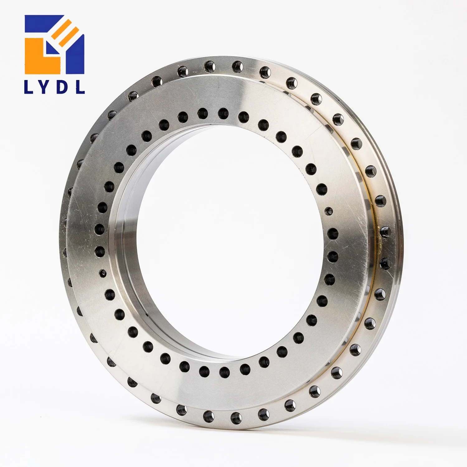
The ZKLDF325 rotary table bearing is LYDL’s double-row angular-contact ball bearing with a 325 mm nominal bore, 450 mm outside diameter and 60 mm overall height. A designer may consider this size when a rotary axis needs a large central opening within a relatively shallow axial arrangement. The opening, fixing circles and supporting flange need to be developed together: a large hollow centre leaves less freedom to position reinforcing material near the axis.
Consult the ZKLDF series dimensions for the complete ten-model range. This page uses those published nominal figures and explains the 325-size installation questions. The final supplied configuration and tolerances require the accepted LYDL drawing.
| Parameter | Symbol | Value | Unit |
|---|---|---|---|
| Bore diameter | d | 325 | mm |
| Outside diameter | D | 450 | mm |
| Overall height | H | 60 | mm |
| Ring profile reference | H1 | 40 | mm |
| Inner fixing pitch circle | J | 342 | mm |
| Outer fixing pitch circle | J1 | 430 | mm |
| Inner fixing holes | nI × d1 | 34 × Ø9.3 | quantity × mm |
| Outer fixing holes | nA × d3 | 33 × Ø9.3 | quantity × mm |
| Inner counterbore diameter | d2 | 15 | mm |
| Counterbore depth | a | 8.2 | mm |
| Extraction thread reference | G | M12 | metric |
| Extraction positions | — | 3 | quantity |
| Retaining screw reference | — | 2 | quantity |
| Published mass reference | m | 28 | kg |
Dimensions and mass: LYDL series table. Symbols follow its structure diagram. Mass is a reference; drawing approval defines the supplied unit. Load ratings, limiting speed, preload and numerical tolerances require configuration-specific confirmation.
Subtracting the 325 mm bore from the 450 mm outside diameter gives 125 mm across both sides, or 62.5 mm nominal radial section per side. ZKLDF260 has the same calculated section but a smaller overall diameter. Equal boundary-section values do not prove equal ring stiffness, load capacity or support requirements; the entire geometry and its connection to the machine differ.
At 60 mm overall height, ZKLDF325 adds 5 mm over ZKLDF260. Its H1 profile reference is 40 mm. Preserve the distinction between those values when locating a rotating platter and any stationary protective cover. Add the actual support shoulders and their tolerances to the stack instead of deriving them from the nominal outside envelope.
The listed inner and outer fixing circles are 342 and 430 mm. Fixing quantities are 34 inner and 33 outer holes, with 9.3 mm hole diameters. These circles identify where fastening acts, but they do not by themselves identify the full contact areas between the bearing and supporting flanges. Review the detailed seat and ring section before setting the carrier wall thickness.
If the machine uses an annular table, check how the support annulus connects to the rest of the casting or frame. Large access windows, segmented brackets or local pockets can make that connection uneven around the circumference. The practical question is whether the loaded support deflects consistently enough for the machine’s accuracy requirement, not whether an unloaded bearing can be bolted into place.
Include screw-head recesses, thread engagement and service-tool access in the review. ZKLDF325 lists a 15 mm inner counterbore diameter and 8.2 mm depth. Ensure adjacent equipment does not block the intended tool path after the motor and cover are installed. Reserve the extraction features for their defined service purpose and confirm their angular positions on the drawing.
| Model | Bore d | Outside D | Height H |
|---|---|---|---|
| ZKLDF260 | 260 | 385 | 55 |
| ZKLDF325 | 325 | 450 | 60 |
| ZKLDF395 | 395 | 525 | 65 |
ZKLDF260 reduces the bore by 65 mm and outside diameter by 65 mm while using a 55 mm height. ZKLDF395 increases the bore by 70 mm and outside diameter by 75 mm, with 65 mm overall height. These options alter the central passage and outer structure together. They should be evaluated against the completed mechanism rather than as isolated diameter choices.
A YRT325 roller-bearing assembly occupies the same quoted principal dimensions as ZKLDF325. Review the differences in rolling architecture and operating requirements before treating it as a potential alternative. The YRT technical family page provides that context. A drawing comparison remains necessary even when d, D and H agree exactly.
An annular platform may need its centre open for a process head, inspection access or service connection. ZKLDF325 can be considered as its rotary support when the required loads and motion justify this bearing concept. Define how the workholding load reaches the bearing and where the stationary structure reacts it into the machine frame.
A fixture spanning the open centre may flex in a different way from the surrounding ring. Include both parts in the support assessment. If the part sits at a significant height above the bearing plane, a lateral process force also creates an overturning moment. Record that lever arm explicitly; the bore diameter is not a substitute for the force-to-bearing distance.
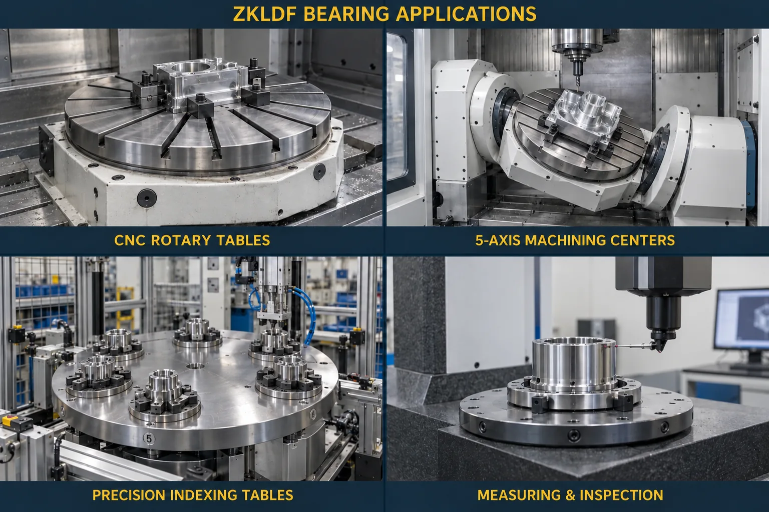
Specify the rotating plate, fixture and workpiece as one moving assembly when considering balance and acceleration. A bearing’s reference mass does not provide the polar inertia of the complete machine. Use the actual geometry and mass distribution to determine the drive demand, and check whether workpiece changes alter the balance or the most demanding load case.
For continuous rotation, discuss temperature development and lubricant requirements with the actual speed cycle. For indexing, include acceleration, braking, dwell and direction changes. Agree a permitted operating range for the supplied unit rather than assuming a speed from a similar-looking component. Also document whether the surrounding support is exposed to process heat or motor cooling gradients.
State P5, P4 or P2 if that is the precision requirement for quotation, then identify the numerical limits and measurement datums to be accepted. Component accuracy, installed-axis runout and angular positioning should be specified separately. A high-resolution encoder cannot correct every form of support-face deformation or workholding movement.
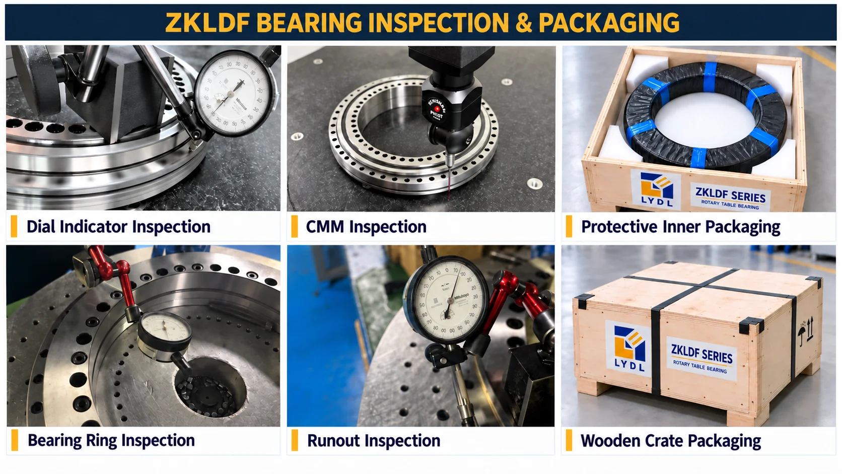
Inspection requirements for ZKLDF325 should address the complete model identity, dimensions, fixing references and agreed running-accuracy features. Ask for an intelligible record linked to the item identification. Define measurement support and clamping conditions if the customer’s machine test will use a different arrangement from the component inspection fixture.
The published mass reference is 28 kg. Use it when planning the receiving area, while confirming the actual package and handling method for the delivered configuration. Support the assembly securely and protect finished faces against abrasive debris. The common graphic illustrates inspection and shipping protection; it is not an inspection certificate or an illustration of a size-specific completed shipment.
Only the nominal bearing bore is specified here. Shaft walls, centre services and supporting parts can reduce the machine opening. Draw the entire passage and include installation and maintenance access before selecting internal equipment.
The bearing can only retain its intended installed behaviour when the surrounding connection is suitable. Windows, pockets or segmented supports may cause uneven deformation, so review the path from the fixing area into the main structure.
They share some nominal hole and section values, but their bores, outside diameters, heights and fixing circles differ. Matching a few figures is insufficient for reuse of an adapter or housing without checking both complete drawings.
No. Drive demand depends on the inertia of the rotating parts and their distribution about the axis, plus the motion profile and other torques. Include the platter, fixture, workpiece and coupled drive components in that calculation.
The total height H is 60 mm. H1 is the separate 40 mm profile reference. Add the adjacent flange, cover and interface details explicitly when calculating the complete axial installation stack.
Send LYDL your requirements with the support section, moving assembly and operating cycle. Browse the rotary bearing overview for other family options. The Schaeffler architecture reference explains general terminology; the LYDL order documents determine the delivered bearing and its acceptance.
Email: sales@luoyangdeeplink.com. Browse the ZKLDF product category for published family entries.