

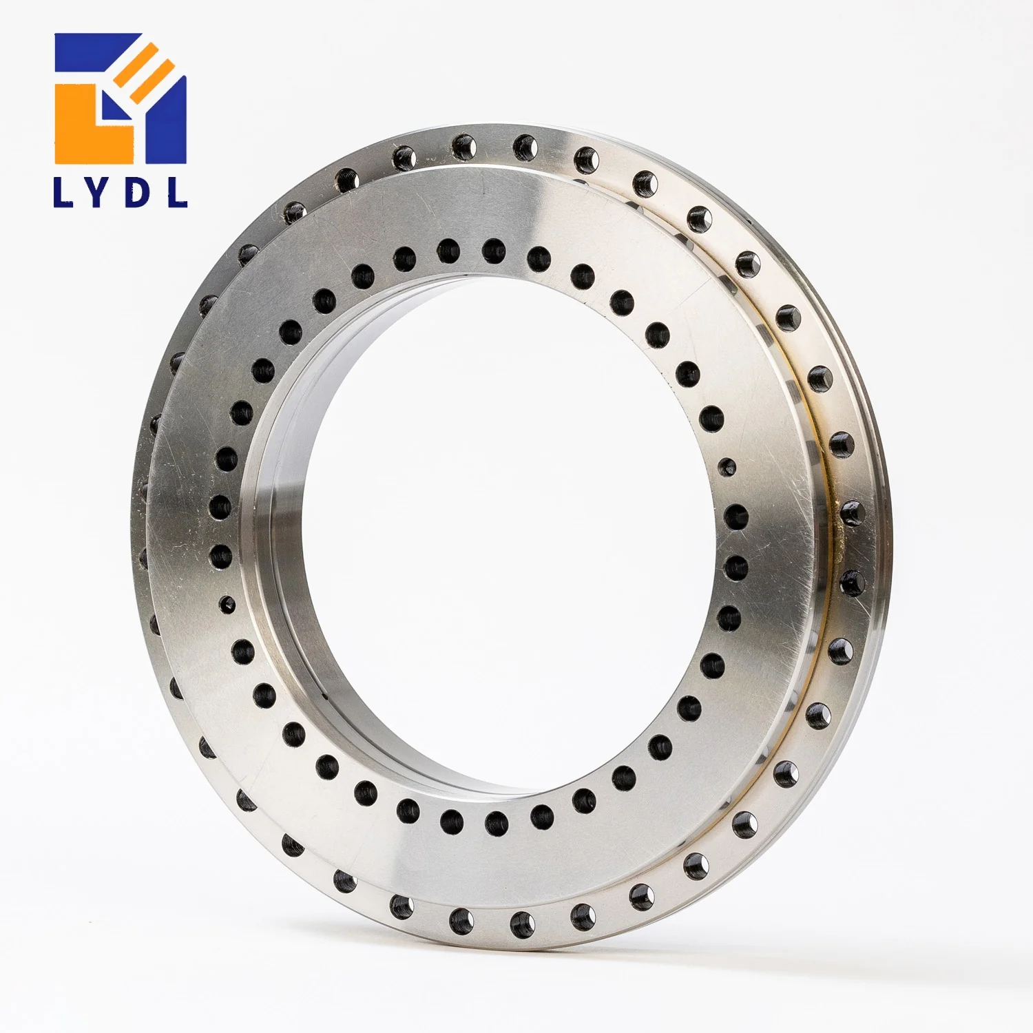
The LYDL ZKLDF260 rotary table bearing has nominal dimensions of 260 × 385 × 55 mm. It uses the ZKLDF double-row angular-contact ball concept to support a rotating assembly carrying combined axial, radial and moment loads. This size introduces a larger radial section and a different fixing arrangement from ZKLDF200. It therefore deserves a dedicated housing and flange review, particularly when a project combines a central passage with a substantial peripheral drive or workholding plate.
The dimension set comes from the published ZKLDF family selection. It identifies the model for layout and enquiry; a released LYDL drawing establishes the actual supply interfaces and acceptance requirements.
| Parameter | Symbol | Value | Unit |
|---|---|---|---|
| Bore diameter | d | 260 | mm |
| Outside diameter | D | 385 | mm |
| Overall height | H | 55 | mm |
| Ring profile reference | H1 | 36.5 | mm |
| Inner fixing pitch circle | J | 280 | mm |
| Outer fixing pitch circle | J1 | 365 | mm |
| Inner fixing holes | nI × d1 | 34 × Ø9.3 | quantity × mm |
| Outer fixing holes | nA × d3 | 33 × Ø9.3 | quantity × mm |
| Inner counterbore diameter | d2 | 15 | mm |
| Counterbore depth | a | 8.2 | mm |
| Extraction thread reference | G | M12 | metric |
| Extraction positions | — | 3 | quantity |
| Retaining screw reference | — | 2 | quantity |
| Published mass reference | m | 22 | kg |
Dimensions and mass: LYDL series table. Symbols follow its structure diagram. Mass is a reference; drawing approval defines the supplied unit. Load ratings, limiting speed, preload and numerical tolerances require configuration-specific confirmation.
A 260 mm nominal bore does not mean the assembled axis leaves that entire diameter unobstructed. A hollow shaft, support sleeve or rotary-service housing occupies part of the opening. Define the smallest required clear passage and trace it through the full machine section. Check connector removal and service access as well as the size of the components during normal operation.
The 385 mm outside diameter leaves a calculated nominal radial section of 62.5 mm. That value helps assess the boundary envelope, but the shoulder geometry must come from the ring profile. The listed 36.5 mm H1 reference should also be positioned on the correct face; the complete bearing height is 55 mm. Keep these two values separate in the tolerance stack.
ZKLDF260 lists 34 inner-ring and 33 outer-ring fixing holes, compared with 46 and 45 for ZKLDF200. Its fixing-hole diameters increase to 9.3 mm and the pitch circles become 280 and 365 mm. This is a clear example of why a designer should not extrapolate drilling quantities or screw details from the previous bore size.
The inner counterbore reference is 15 mm diameter by 8.2 mm depth. Confirm how the intended fastener head, washer policy and installation tool relate to that recess on the released drawing. Check thread engagement in the adjacent component using its material and complete wall section. A catalogue mounting value from another bearing brand is not an automatic tightening instruction for the LYDL assembly.
If a carrier contains motor cooling channels or a rotary-union pocket near the bearing seat, include them in the stiffness assessment. Their position can interrupt the load path behind a fixing location. Inspect the support faces and mating location before assembly, then record the condition after the complete clamping sequence. Do not use the bearing screws to correct an inaccurate carrier face.
| Model | Bore d | Outside D | Height H |
|---|---|---|---|
| ZKLDF200 | 200 | 300 | 45 |
| ZKLDF260 | 260 | 385 | 55 |
| ZKLDF325 | 325 | 450 | 60 |
Moving from ZKLDF200 to this size increases the nominal bore by 60 mm and the height by 10 mm. The next model, ZKLDF325, increases the opening by another 65 mm while changing the height to 60 mm. Neither change should be justified by the bearing name alone. Establish the service passage, supporting geometry and calculated load requirements before selecting the larger envelope.
The YRT260 roller support is a useful same-envelope comparison. Ask how the two constructions affect the required motion, mounted stiffness and lubrication plan for your axis. The YRT family overview separates the different roller-series functions. Shared outside dimensions do not show that a complete ZKLDF260 and YRT260 assembly can be exchanged without checking details.
A possible application is a rotary positioning axis with process services passing through a hollow centre. The services might include cables, pneumatic lines or a rotary union, while the bearing carries the rotating fixture and loads from the process. The drawing should identify which structure rotates and which connections remain stationary.
Place the workpiece centre of gravity and all force application points on the load sketch. An overhung fixture can produce a large moment even if its main force lies along the nominal axis. During rotation, hoses and cables may also apply variable forces. Check them at their most restrictive position rather than assuming a central route is automatically free of disturbance.
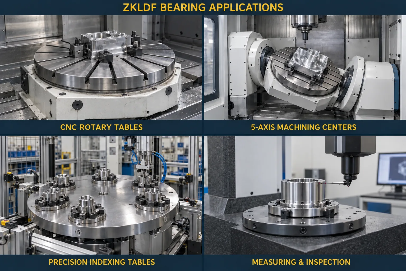
Describe whether the bearing works in a horizontal table, vertical faceplate or changing-orientation assembly. Gravity acts differently on the surrounding fixture in each case. Review the load components over the entire motion range and identify any assembly or maintenance position that differs from normal operation. Do not use a horizontal application photograph as evidence for every orientation.
Provide the speed profile and operating duration, including slow motion, repeated starts and stationary loading. Permissible speed and lubrication must be agreed for the actual supplied bearing. If a torque motor surrounds the carrier, add cooling details and expected temperature differences. Stable room temperature alone does not establish a stable condition inside the assembled bearing position.
Choose the required precision specification during quotation, with P5, P4 or P2 stated where relevant to the project. Identify the particular runout measurements and their datums rather than relying only on the grade label. The accuracy of the finished mechanism also depends on the supporting structure, fixture and feedback system, which are outside the bearing’s nominal size table.
For ZKLDF260, a useful purchase specification ties the item designation to the boundary dimensions, fixing interfaces and accepted accuracy record. State any reporting requirements before production. If the machine team intends to compare component and assembled-axis readings, make their clamping conditions and measurement locations explicit so differences can be interpreted.
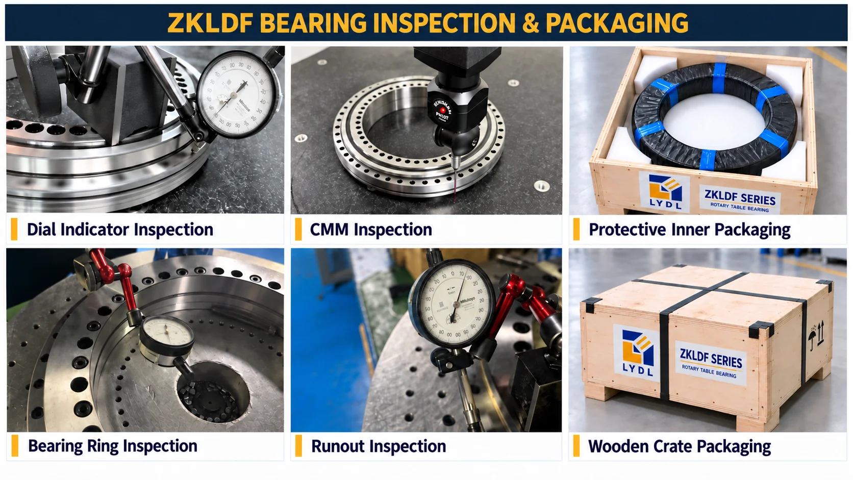
The reference mass in the selection table is 22 kg. It supports initial handling planning; determine actual lifting arrangements from the supplied assembly and its packaging. Agree corrosion protection and transport support, keep the rings protected from loose hardware, and inspect the package before unpacking. The image below explains generic inspection and packaging activities rather than proving that a particular bearing has completed them.
The published interfaces differ by model: ZKLDF260 uses thirty-four inner and thirty-three outer fixing holes with larger hole diameters. Copy the complete size-specific pattern from the drawing rather than expecting hole quantity to rise with bore size.
Using its 385 mm outside diameter and 260 mm bore gives 62.5 mm on either side. This boundary calculation does not identify the usable shoulder or replace the actual stepped ring profile.
The bearing bore alone cannot answer that. The hollow shaft wall, sleeves, fastener clearances and connections may reduce the effective opening. Check the complete passage and the removal path in the machine section.
Its suitability depends on the loads and supporting geometry in the intended orientation. Supply the full force and moment diagram, including gravity and movement through the operating range, so the configuration can be reviewed specifically.
Use the listed twenty-two-kilogram mass only as an initial reference. Confirm the actual package mass, lifting method and protective support for the supplied unit, especially if accessories or a mounting flange are included.
Use LYDL’s enquiry contact to provide your axis drawing, load cases and intended precision. The rotary table bearing catalogue offers wider family navigation. Schaeffler TPI 120 terminology is an external concept reference, not the acceptance document for an LYDL bearing.
Email: sales@luoyangdeeplink.com. Browse the ZKLDF product category for published family entries.