

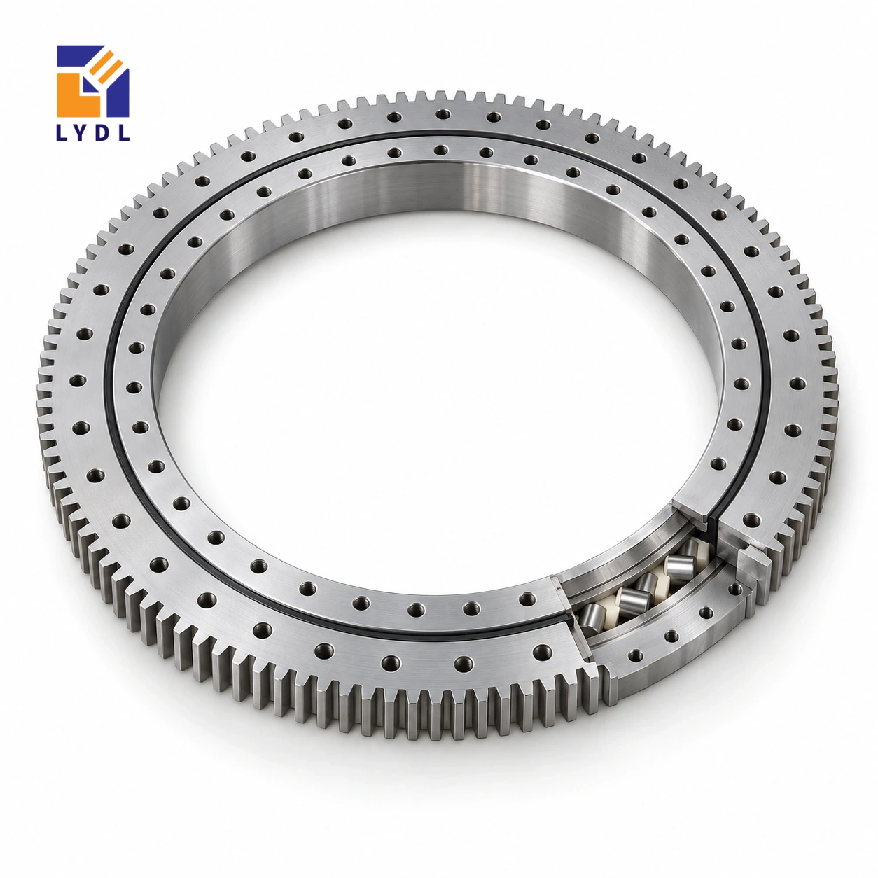
The XA140640 externally geared slewing reference measures 571 × 742.3 × 50 mm in the LYDL table. Its module 6, 122-tooth gear shares some transmission numbers with XSA140644, while the mounting and bore dimensions remain different.
XA140640: nominal LYDL listing. INA interchange unverified. Supplied execution requires an agreed drawing.
XA specification tables · Family technical reference
| Bore (mm) | Outside (mm) | Height H (mm) | Mass ≈ (kg) |
|---|---|---|---|
| 571 | 742.3 | 50 | 50 |
| Outer PCD La (mm) | Inner PCD Li (mm) | Outer holes na | Hole dB (mm) | Secondary h (mm) |
|---|---|---|---|---|
| 685 | 595 | 44 | 13 | 43 |
| Pitch d0 (mm) | Module m (mm) | Teeth z | Width b (mm) |
|---|---|---|---|
| 732 | 6 | 122 | 43 |
Compare the 571 mm XA bore with the 574 mm XSA140644 reference bore, and the 50 mm XA height with the 56 mm XSA height. The current XA row lists forty-four outer fixing positions, whereas the XSA reference has a different outer count. These differences matter even when the external gear has the same 732 mm pitch diameter. Overlay the original machine section and connection drawings before selecting a replacement strategy.
The XA fixing circles are listed as 685 mm and 595 mm with 13 mm holes. Confirm the full inner pattern, location features and screw access instead of borrowing details from the XSA family.
Identify the feed centreline, platform working surface and drive-axis location as equipment datums before comparing a replacement. An outside-gear match can preserve a nominal pinion position while leaving the feed or upper plate misaligned. Trace the axial stack through the bearing, adapter and mating plates and state where adjustment is permitted. If the existing feed is fixed to the base, distinguish its load path from forces applied by the rotating deck.
Document the permitted bore clearance and the actual pilot arrangement. The three-millimetre nominal bore difference from XSA140644 should be evaluated at the relevant features rather than assumed to be either harmless or decisive. Compare the forty-four outer fixing positions with the existing flange, including abandoned holes and dowels. Their local arrangement may govern whether an adapter is practical.
For operation, provide indexed acceleration and the stopped loads from filling, sealing or alignment. Specify where system movement is measured if positioning behaviour motivates the change. The proposed bearing execution must be assessed alongside support and transmission behaviour. Once an arrangement is selected, keep the supplied drawing revision consistent with the machine modification and inspection record.
The XA140640 gear row describes external teeth with module 6 and 122 teeth. Their product is 732 mm, matching the listed nominal pitch diameter. That arithmetic checks the relationship between three entries; it does not calculate a permissible tooth force. The physical outside diameter is 742.3 mm and the bore is 571 mm, so neither should be replaced by the pitch-circle value in a clearance drawing. Overall height H is 50 mm. Locate the gear face and the two mounting planes from the offered section before positioning a pinion. The tooth form, engagement, quality requirement and supplied material execution remain separate specification items. Keeping these definitions distinct prevents a correct transmission number from being used as the wrong housing dimension.
The geometry combines a 571 mm bore with 50 mm overall height and a 742.3 mm outside envelope. For an open-centre platform, draw the stationary equipment and its service movements through the opening. Include the flange stack above and below the ring. The available working height is determined by the assembled parts, not just H.
Review the connection and pinion access while the central equipment is present. A design can provide generous radial clearance yet leave no route for a tightening tool or replacement motor. Establish which items are installed first and which can later be removed independently. These practical constraints help decide whether the nominal envelope suits the proposed machine.
A wide opening leaves an annular structure supporting the fixture. Show the actual plate sections, ribs and joints under both attachment zones. Include any additional openings for cables or service tools. Do not assume the stiffness of a solid plate where the real part contains extensive cutouts.
Place process forces and tooling centres of gravity on the same drawing, with their application heights. Define the required result at the working point, especially if it is far from the axis. Ask for review of the complete support arrangement against the duty. The approximate 50 kg component mass and the nominal radial dimensions do not establish load capacity, flange stiffness or an allowable displacement.
Both rings list forty-four attachment positions, on circles of 685 mm and 595 mm. The large count makes it useful to check angular orientation and tool access early. Add the agreed screw and locating details, then inspect whether the backing is continuous near each region of the pattern. Fastener quantity cannot compensate automatically for an unsuitable seating.
The external mesh has module 6 and 122 teeth on a 732 mm pitch circle. Identify the proposed pinion and support, and locate it against the listed 43 mm gear face in the offered section. Describe the required motion and reversal behaviour. Any tooth-force, quality or positioning requirement must be resolved for that actual transmission.
Send the mating drawings and the dimensions that cannot change when enquiring about XA140640. The nominal source is LYDL's row; a full independent original-brand correspondence has not been verified for this extended model. A supplier proposal should identify the offered revision before a replacement decision is recorded.
State the operating environment and the requested inspection scope. Separate received-component checks from the loaded platform observation and keep their conditions with the results. Protect the annular seating and external teeth during delivery and storage. For repeat supply, retain the accepted pinion and flange information with the bearing identity so compatibility is assessed against a defined machine.
XA240685 has a 577 mm bore, only slightly above the 571 mm opening here, but increases the outside envelope to 830.1 mm and H to 68 mm. It uses module 8 with 102 teeth instead of module 6 with 122 teeth. The two references also have markedly different fixing patterns.
Draw the full machine boundary and working plane when comparing them. A nearly equal opening is a weak basis for retaining a pinion bracket or flange. Determine whether the central equipment is the governing constraint and which surrounding parts can actually change. Seek the offered section and application review for the candidate that meets those constraints, keeping nominal LYDL geometry separate from an unverified interchange assumption.
Retain the flange drawing with its access windows and local recesses. A later pocket introduced for maintenance should be reviewed against the support geometry used for the original proposal.
A rotary packaging deck surrounding a large feed opening is one possible study. The bore and height differences should be checked against feed alignment and the required working level.

Define which flange surfaces control working height and concentricity. Request matching identification on any measurement report and protect both pilots and external teeth for shipment.

No. Their cited bores are 571 and 574 mm and their heights 50 and 56 mm, despite the shared outside gear size.
The references list module 6, 122 teeth and a 732 mm pitch diameter. Full gear compatibility still requires drawing review.
Forty-four positions on a 685 mm circle, with 13 mm hole diameter; the listed inner circle is 595 mm.
Changing the axial stack can shift tooling or product-feed alignment. Check the complete assembly rather than only the bearing height.
No. It is an extended LYDL listing whose supplied dimensions and performance must be agreed for the order.
Pinion inside: XI series. Standard external-gear group: XSA range.
Send XA140640 enquiries with the existing working-height datum and both flange patterns marked.