

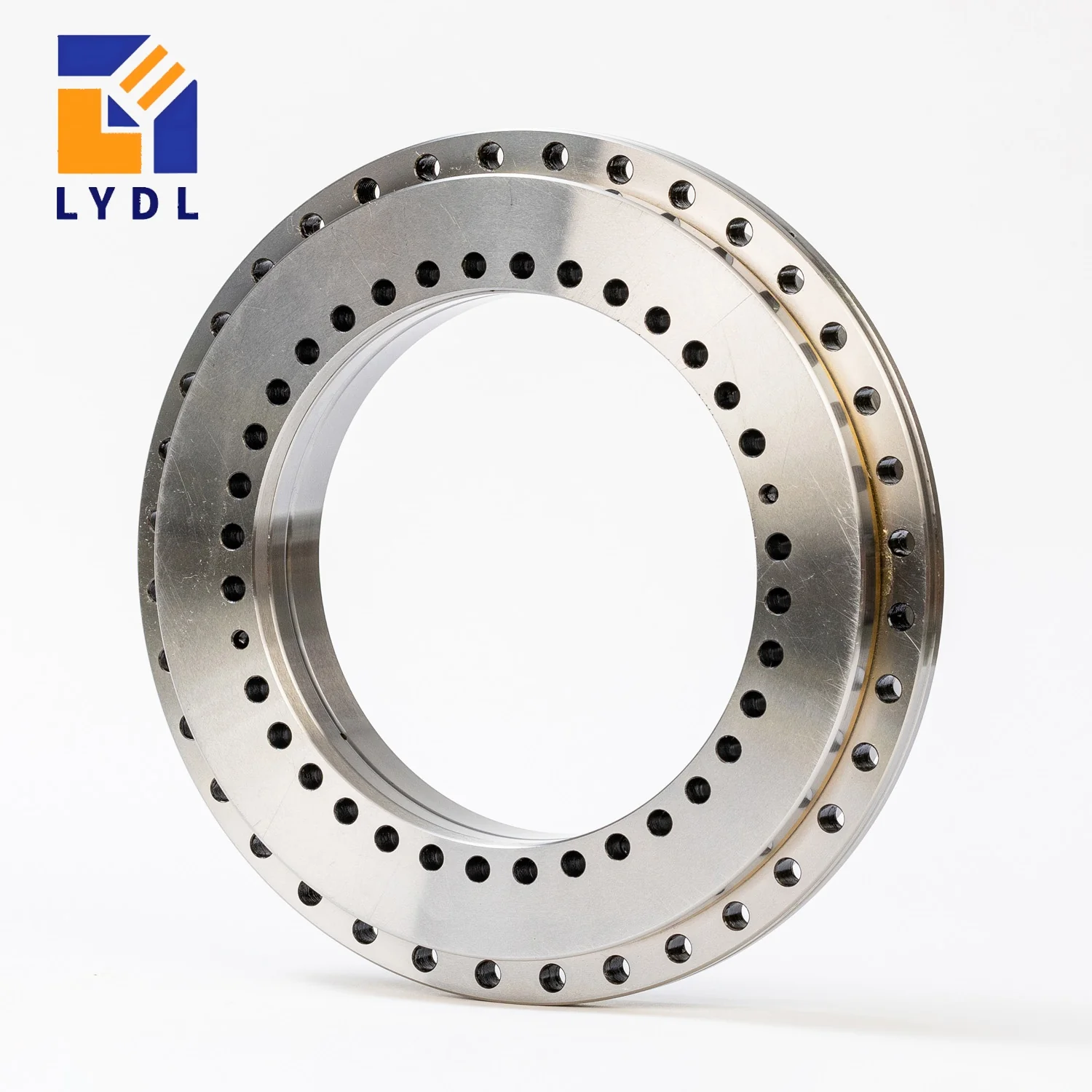
The ZKLDF395 rotary table bearing listed by LYDL measures 395 mm at the bore, 525 mm at the outside diameter and 65 mm in overall height. Its double-row angular-contact ball architecture is a candidate for combined-load rotary axes where motion behaviour, mounting stiffness and available space must be reviewed together. The 395 size also marks a change in fixing-hole quantity from ZKLDF325, an important distinction when adapting an existing carrier design.
Refer to the ZKLDF selection guide for the published model data. Nominal dimensions support the initial design discussion; the accepted LYDL drawing establishes the delivered interfaces, precision requirements and order configuration.
| Parameter | Symbol | Value | Unit |
|---|---|---|---|
| Bore diameter | d | 395 | mm |
| Outside diameter | D | 525 | mm |
| Overall height | H | 65 | mm |
| Ring profile reference | H1 | 42.5 | mm |
| Inner fixing pitch circle | J | 415 | mm |
| Outer fixing pitch circle | J1 | 505 | mm |
| Inner fixing holes | nI × d1 | 46 × Ø9.3 | quantity × mm |
| Outer fixing holes | nA × d3 | 45 × Ø9.3 | quantity × mm |
| Inner counterbore diameter | d2 | 15 | mm |
| Counterbore depth | a | 8.2 | mm |
| Extraction thread reference | G | M12 | metric |
| Extraction positions | — | 3 | quantity |
| Retaining screw reference | — | 2 | quantity |
| Published mass reference | m | 39 | kg |
Dimensions and mass: LYDL series table. Symbols follow its structure diagram. Mass is a reference; drawing approval defines the supplied unit. Load ratings, limiting speed, preload and numerical tolerances require configuration-specific confirmation.
The 525 mm outside diameter and 395 mm bore give a nominal 65 mm radial section on either side. This calculated boundary relationship is useful for comparing layouts, but it does not define an allowable supporting shoulder or establish the stiffness of a completed carrier. Use the actual stepped section when placing the locating faces and fasteners.
The height reference H1 is 42.5 mm, distinct from the 65 mm total height. On a machine with a separate table clamp or brake, show its axial location relative to the bearing faces. The brake carrier, housing cover and rotating flange all add their own dimensions and tolerance contributions. They should be visible in the same section before machining the main housing.
ZKLDF395 lists 46 inner-ring fixing holes on a 415 mm pitch circle and 45 outer-ring holes on a 505 mm pitch circle. By comparison, ZKLDF325 uses 34 and 33 fixing holes. The increase is a discrete interface change, not a reason to scale an existing drilling program without checking its angular references and auxiliary positions.
The fixing-hole diameter is 9.3 mm on both rings in the published table. The inner counterbore is 15 mm diameter with 8.2 mm depth. Check the proposed screw head and tool against those recesses, the adjacent parts and the approved stack. Determine assembly instructions for the complete connection; the bearing designation does not independently define thread engagement or a safe tightening torque.
Create an accessible fastening sequence before adding guards, the drive and lubrication connections. If any screw becomes inaccessible after an assembly step, resolve that conflict in the process plan. Retaining screws and extraction threads should remain correctly identified so they are not mistaken for general attachment locations on a crowded machine interface.
| Model | Bore d | Outside D | Height H |
|---|---|---|---|
| ZKLDF325 | 325 | 450 | 60 |
| ZKLDF395 | 395 | 525 | 65 |
| ZKLDF460 | 460 | 600 | 70 |
The increase from ZKLDF325 adds 70 mm to the bore, 75 mm to the outside diameter and 5 mm to the total height. The next listed size, ZKLDF460, adds 65 mm of bore and 75 mm of outside diameter, with 70 mm overall height. The choice affects the carrier, table and service passage at the same time.
For an alternative construction, the YRT395 page describes a roller-bearing support at the same nominal boundary size. Use the YRT group reference to compare family functions before deciding which architecture suits the operating task. Exact hole positions, ring profiles, lubrication, preload and installed accuracy must still be checked model by model; equal boundary dimensions are only the beginning of that review.
Consider a rotary table that indexes a fixture, reverses direction and holds position while a process acts on the component. ZKLDF395 can be evaluated as the mechanical rotary support. The working load diagram should include the fixture’s weight, centre of gravity and any process force acting away from the bearing plane.
Reversal introduces drive and control demands that are different from carrying a stationary load. Calculate the inertia of the whole rotating assembly and specify the intended acceleration and deceleration. Include off-centre workpieces and changes between fixtures. The bearing’s nominal dimensions or reference mass cannot determine the completed table’s acceleration requirement, and the illustration below is not a record of a tested customer machine.
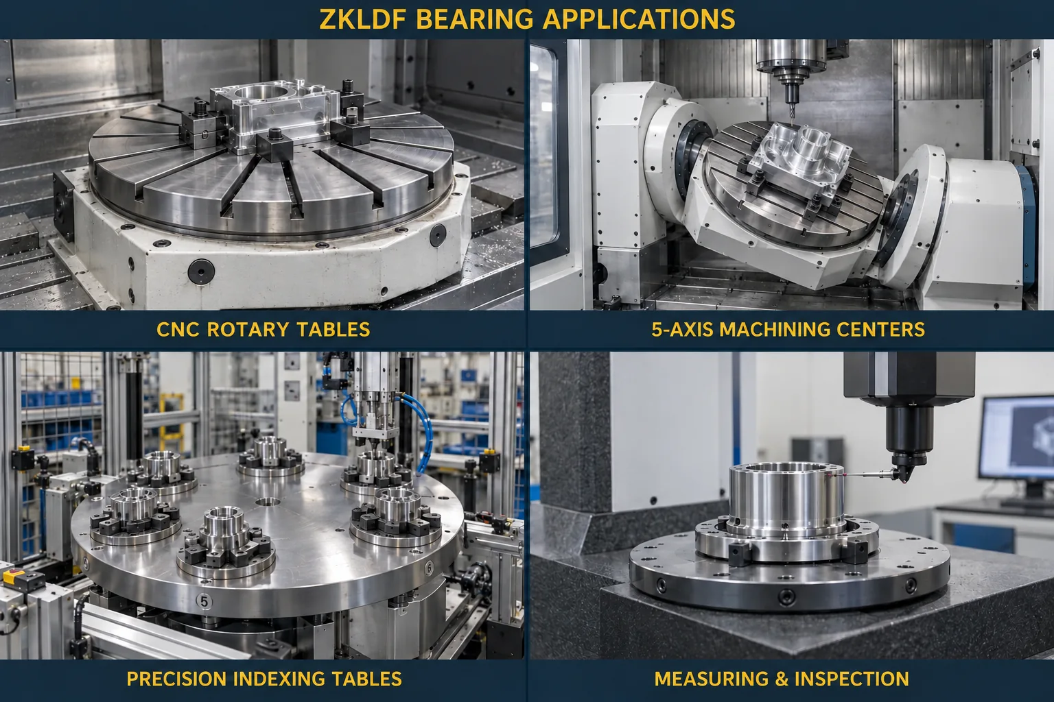
If a brake or clamp holds the axis during processing, identify how its force enters the rotating and stationary structures. It may alter the deformation state around the bearing. Compare relevant accuracy readings with the clamp released and engaged using the same measurement datum, and include any significant change in the machine’s acceptance review.
Describe the operating sequence with enough detail to evaluate lubrication and heat: movement angle, number of reversals, running time, dwell and speed during transfer. A component’s catalogue limiting speed does not describe its whole duty cycle. Ask LYDL to confirm the applicable operating conditions for the supplied ZKLDF395 rather than presenting a different manufacturer’s values as a guaranteed capability.
For precision, state the requested P5, P4 or P2 requirement and the actual running-accuracy limits needed by the project. The feedback system, table geometry and control settings determine additional parts of the positioning result. Keep component inspection criteria separate from the measured behaviour of the complete axis, particularly when workholding and clamping forces change between tests.
The series table gives a 39 kg reference mass for ZKLDF395. Confirm the delivered assembly and package mass before choosing handling equipment or planning the receiving fixture. Agree suitable support, protect finished faces and do not assume that a convenient threaded feature is an approved lifting point. The handling method should be established for the actual unit.
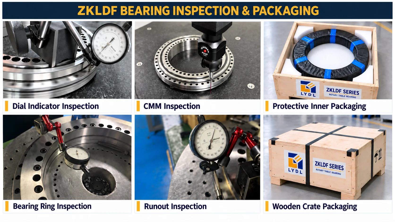
Inspection documentation can cover identification, nominal dimensions, fixing interfaces and agreed runout measurements. Define the required record and its datum conditions during ordering. The shared process graphic shows inspection and packing concepts only. It does not demonstrate the result of a test on the bearing you will receive or confirm a specific shipping arrangement.
The listed fixing-hole quantities change from thirty-four/thirty-three to forty-six/forty-five, and the pitch circles also change. Confirm both the counts and angular layout on the ZKLDF395 drawing before adapting an existing carrier program.
Use the drawing’s actual feature layout. A fixing-hole quantity does not independently describe auxiliary positions, interruptions or the angular starting datum. Do not reconstruct the pattern from the quantity alone.
Show where the clamp loads enter the surrounding structures and compare the relevant fitted-axis measurements in the intended clamping states. A clamp may change deformation even when it does not directly fasten to the bearing.
No. The drive calculation needs the inertia of all rotating parts, their radial distribution and the motion profile. It also needs the other torques in the assembly; the bearing’s mass is only one component reference.
Provide the moving assembly, workpiece offsets, rotation angle, reversal frequency, acceleration, process loads and clamping sequence. Combine those details with the mounting section and requested running accuracy so the review reflects the actual task.
Contact LYDL about this size with your table section and operating sequence. The rotary table bearing family page provides broader navigation. Consult Schaeffler’s structure publication for independent terminology, while retaining the LYDL drawing as the supply and acceptance reference.
Email: sales@luoyangdeeplink.com. Browse the ZKLDF product category for published family entries.