

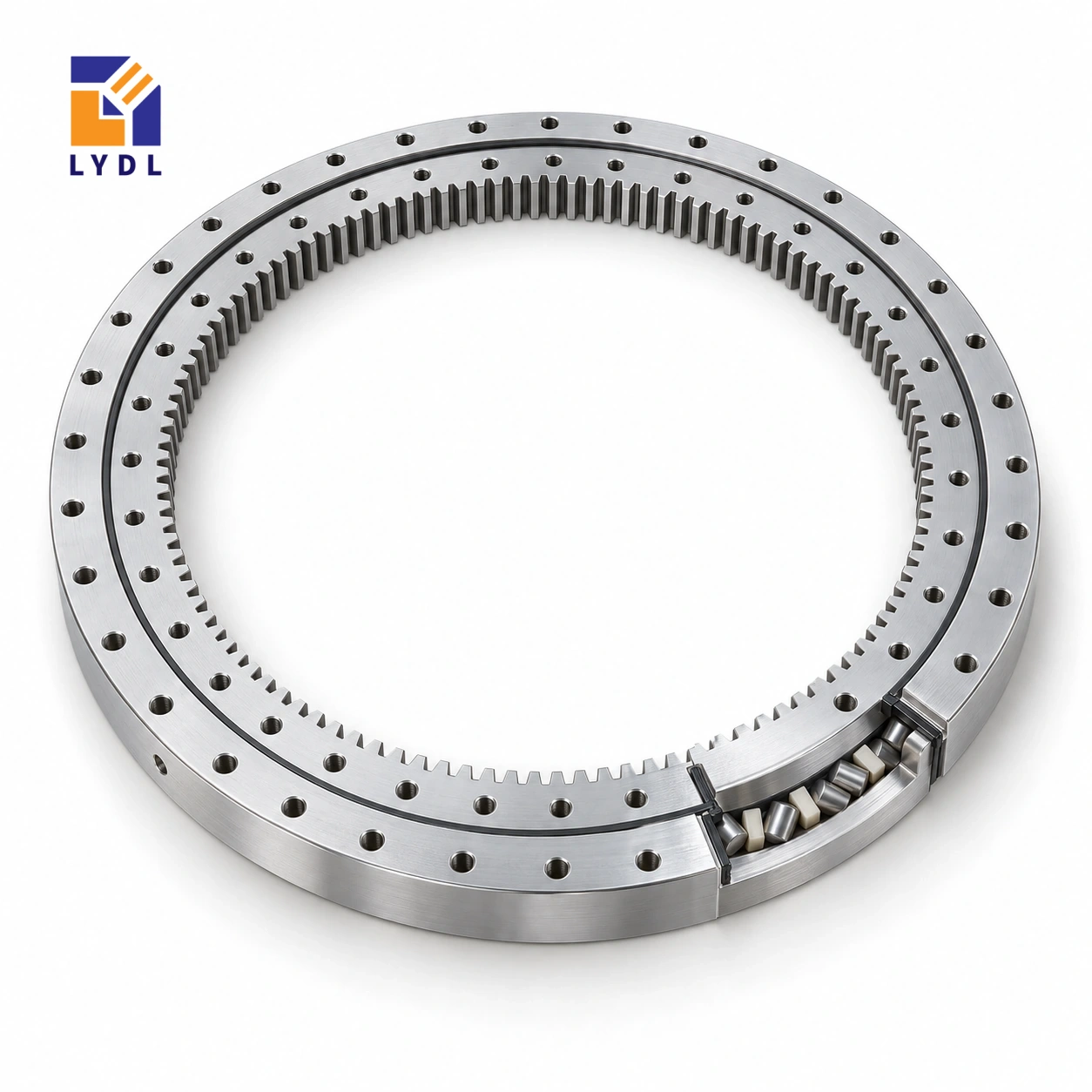
XSI140744 is an internally geared crossed roller reference with a 648 × 814 × 56 mm envelope. The listed gear has module 6 and 110 teeth, and both rings use forty fixing positions on different mounting circles.
XSI140744: LYDL table; original height from Catalogue 404, pp. 84–85. Ordered execution requires drawing agreement.
XSI specification tables · Family technical reference
| Bore (mm) | Outside (mm) | Height H (mm) | Mass ≈ (kg) |
|---|---|---|---|
| 648 | 814 | 56 | 58 |
| Outer PCD La (mm) | Inner PCD Li (mm) | Outer holes na | Inner holes ni |
|---|---|---|---|
| 790 | 705 | 40 | 40 |
| Pitch d0 (mm) | Module m (mm) | Teeth z |
|---|---|---|
| 660 | 6 | 110 |
An internal drive may keep the external perimeter compact, but it does not reduce the moment generated by an offset payload. Locate the payload centre and any process force relative to the bearing plane at every operating position. The 660 mm pitch diameter describes the mesh, while the raceway and bolted joint require a separate combined-load assessment. Include bracket flexibility when defining the platform’s angular displacement requirement.
Use 790 mm and 705 mm fixing circles for the reference comparison. Check the access path to forty inner screws alongside the pinion and its support, including the removal sequence for the guard.
Choose a working datum on the fixture and define the external load used to judge movement there. Separate the contribution of fixture bending, supporting-plate deformation and motion at the rotary connection where the design review permits. This prevents a system stiffness concern from being assigned to a single component without evidence. Record the payload configuration that produces the largest lever arm and include any guide or gripper force at height.
Describe normal acceleration and the distinct emergency-stop case. The internal drive geometry should show how its bracket reacts into the base and how it remains aligned as the structure carries those loads. Check the forty inner locations with the bracket, motor and central equipment all present. If inspection access requires an opening, include it in the flange drawing used for assessment.
During commissioning, compare readings under the defined load and support conditions. A free-running component check is valuable for receiving acceptance but cannot establish the loaded performance of the completed tall-fixture assembly.
The XSI140744 gear row describes internal teeth with module 6 and 110 teeth. Their product is 660 mm, matching the listed nominal pitch diameter. That arithmetic checks the relationship between three entries; it does not calculate a permissible tooth force. The physical outside diameter is 814 mm and the bore is 648 mm, so neither should be replaced by the pitch-circle value in a clearance drawing. Overall height H is 56 mm. Locate the gear face and the two mounting planes from the offered section before positioning a pinion. The tooth form, engagement, quality requirement and supplied material execution remain separate specification items. Keeping these definitions distinct prevents a correct transmission number from being used as the wrong housing dimension.
The feed tube and rotating deck should appear in the same section as the internal pinion. Include collars, connectors and any transfer nozzle. The 648 mm nominal bore may provide useful space, but the bracket and drive occupy part of the central region. Check clearance throughout movement and during feed adjustment.
Describe how the feed module is installed and removed. Can it pass through the completed deck, and can tools reach the inner connection while it is present? Establish a supported maintenance state for the deck before releasing the assembly sequence. These questions turn a nominal opening into an equipment layout that can actually be built and serviced.
List the product and fixture positions around the deck, including empty stations and partial occupancy. Show forces from filling, closing, labelling or transfer only where those operations are actually proposed. A process reaction during dwell can differ from the load being accelerated during indexing. Keep their directions and application points in the duty description.
State move angles, cycle timing, reversals and relevant stop conditions. Include the moving tooling and distribution of mass, not only product weight. For an approved recovery operation, describe the action and its force path. The nominal dimensions cannot supply a generic overload allowance for an undefined jam or clearing procedure.
The internal gear row lists module 6 and a 660 mm pitch circle. Specify the actual proposed pinion, its bearings and bracket attachment. Show how the bracket reacts into the base and how engagement is set. The 814 mm outside envelope alone says little about those central installation requirements.
Define the output observation at the product nest after a stated approach and dwell. The result includes deck behaviour, drive response and fixture seating. Ask for the relevant offered execution and a clear test method instead of deriving positioning performance from the gear geometry. Include access for checking the mesh after covers and feed components are installed.
Locate the 790 mm outer circle and 705 mm inner circle independently in the mating drawings. Both list forty attachment positions. Confirm screw seats, engagement and locating details from the accepted supply drawing. Check angular orientation against the pinion bracket and the feed's service outlet.
Review the manufactured support beneath those circles, including access cutouts and frame joints. A late maintenance opening can change local backing and should be included in the review. Inspect the seating in a defined support condition and follow the agreed fastening method. The ring should arrive at a prepared interface rather than serve as a tool for straightening an uncertain flange.
Keep the accepted bearing, feed and drive revisions with the operating schedule. Agree component receiving inspection separately from the completed indexer's test. For the latter, document the station occupancy, product fixture and observation datum. Later changes in product size or transfer method can then be compared with an explicit baseline.
State the actual fragments, dust, cleaning and idle environment when requesting the offered protection. Discuss shipment support for the approximately 58 kg component and keep loose feed hardware separated from machined surfaces. The application image is representative context, not evidence that this exact reference has been approved or tested on the proposed packaging line.
XSI140844 keeps 56 mm nominal H but changes from module 6 and 110 teeth to module 8 and 94 teeth. Its 736 × 914 mm bore/outside pair also differs from 648 × 814 mm here. Both list forty positions per ring, on different fixing circles.
If a feed module needs the larger opening, put its collars and service movement on the proposed section. Recheck the pinion, bracket and plate patterns even where the count or height appears unchanged. The indexing schedule and partial-occupancy cases should follow the chosen layout into the technical enquiry. Similar family features organise the comparison but do not establish interchangeable connections or a preserved drive result.
A material-handling swivel carrying a tall fixture is a representative study. Compare pickup, travel and emergency stopping loads at the largest permitted reach.

Define the unloaded running check separately from the installed platform test. Protect internal teeth, machined faces and confirmed service fittings during receiving and assembly handling.

The nominal bore is 648 mm; the reference outside diameter is 814 mm and overall height 56 mm.
The outer circle is 790 mm and the inner circle 705 mm. Forty positions per ring are listed.
The internal gear lists 110 teeth at module 6 with a 660 mm pitch diameter.
The payload geometry determines that moment. Moving the drive inside the ring does not eliminate the effects of height or eccentricity.
The installed structure can change running behaviour and deflection. State the support, fastening and loading conditions for each acceptance check.
Perimeter drive: XSA series. Separate-drive reference: XSU range.
For XSI140744, supply the tall-fixture load cases and the maximum acceptable angular displacement.