

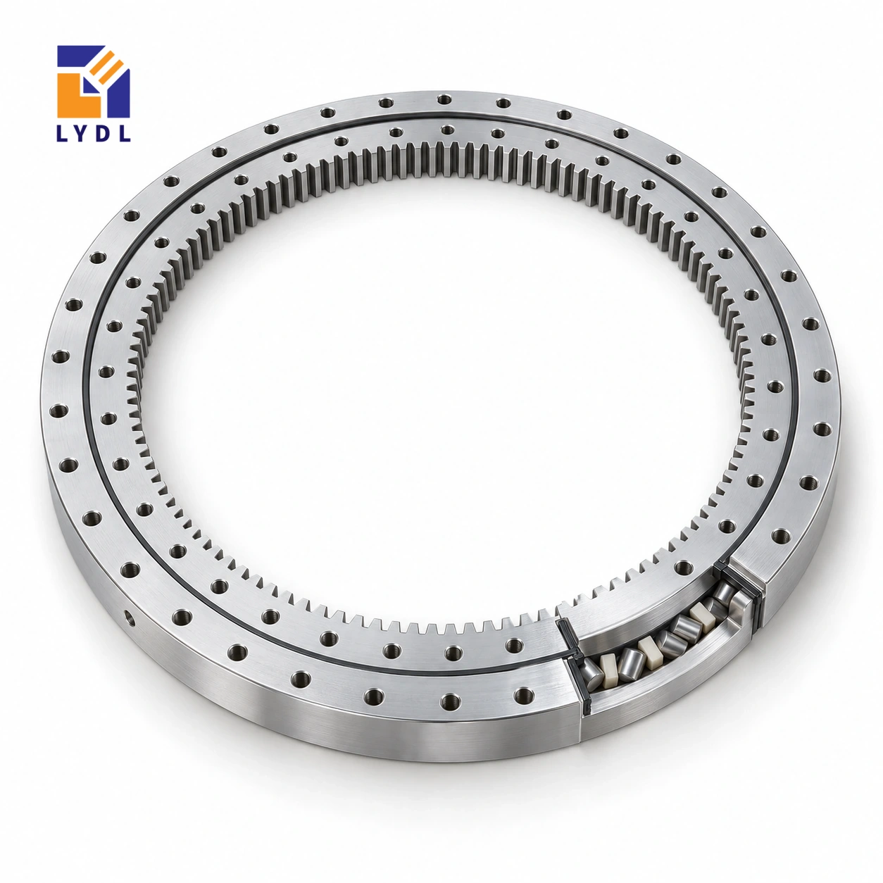
The XSI140644 internal gear slewing reference has a 546 mm bore, 714 mm outside diameter and 56 mm height. Its crossed roller arrangement is listed with module 6 and 93 internal teeth, giving a 558 mm gear pitch diameter.
XSI140644: LYDL table; original height from Catalogue 404, pp. 84–85. Ordered execution requires drawing agreement.
XSI specification tables · Family technical reference
| Bore (mm) | Outside (mm) | Height H (mm) | Mass ≈ (kg) |
|---|---|---|---|
| 546 | 714 | 56 | 50 |
| Outer PCD La (mm) | Inner PCD Li (mm) | Outer holes na | Inner holes ni |
|---|---|---|---|
| 690 | 605 | 36 | 36 |
| Pitch d0 (mm) | Module m (mm) | Teeth z |
|---|---|---|
| 558 | 6 | 93 |
The same-sized XSU140644 reference has a larger 574 mm bore and no integral teeth. XSI140644 uses the centre region differently to accommodate the internal gear. A switch from the gearless arrangement must include the pinion and service-space layout as well as the ring dimensions. Compare fixing circles and locating features independently, then assess whether the supplied execution supports the intended load and running requirements.
The listed outer fixing circle is 690 mm and the inner circle 605 mm, with thirty-six positions per ring. Avoid copying the 598 mm inner circle from XSU140644 into the internally geared design.
If the machine currently uses XSU140644, start by locating its service bundle and both mating plate datums. Overlay the smaller XSI opening and its internal drive rather than changing only the model name on the drawing. Check the moved inner fixing circle and any pilot differences. Identify which components can remain and which need an adapter or new machining.
Review the force transfer through a proposed adapter, including its actual pockets and fasteners. A drive conversion can add bracket reactions that the original ungeared support never carried. Specify where these enter the fixed structure. Keep the performance objective explicit: a compact perimeter, a revised transmission or a measured motion problem each leads to different acceptance questions.
Define the required operating duty and loaded output behaviour before choosing the supplied execution. The full internal mesh needs its pinion, engagement and adjustment details confirmed separately. Finally, plan how those parts and the inner screws can be removed around the retained service equipment. The conversion should be assessed as a complete machine arrangement, not as a bore and outside-diameter substitution.
The XSI140644 gear row describes internal teeth with module 6 and 93 teeth. Their product is 558 mm, matching the listed nominal pitch diameter. That arithmetic checks the relationship between three entries; it does not calculate a permissible tooth force. The physical outside diameter is 714 mm and the bore is 546 mm, so neither should be replaced by the pitch-circle value in a clearance drawing. Overall height H is 56 mm. Locate the gear face and the two mounting planes from the offered section before positioning a pinion. The tooth form, engagement, quality requirement and supplied material execution remain separate specification items. Keeping these definitions distinct prevents a correct transmission number from being used as the wrong housing dimension.
If the station needs light or sensing through the centre, draw the optical equipment beside the internal transmission. The 546 mm bore is a ring dimension, not an unobstructed optical workspace. Include the pinion bracket, covers, connectors and service motions. Identify which components remain fixed as the workpiece rotates.
Define how the nest locates the part and where the inspected feature lies relative to the rotation axis. State whether images are taken during movement or after settling. The inspection result includes optics, workholding and motion as a complete system. Ask for the required installed behaviour at a named datum rather than translating the bearing family into an unsupported optical or precision claim.
Keep Li = 605 mm attached to the inner connection in the equipment drawing. The outer connection uses La = 690 mm, and both rings list thirty-six positions. A copied dimension from a nearby model or a presumed pattern increment can put the correct count on the wrong circle. Use the specific source row and accepted supply drawing.
Add screw details, seats and locating features before manufacturing the flanges. Check access with the optical assembly and pinion in place. Review local backing near service openings and bracket mounts. Document the condition used for seating inspection. The nominal circle and count identify a pattern but do not independently establish the strength or geometric quality of the finished joint.
The nominal internal mesh combines module 6 with a 558 mm pitch diameter. Show the proposed pinion and its shaft support at the correct axial position from the offered section. Include the adjustment travel and a route for replacement. A small motor footprint alone does not represent the whole transmission installation.
Specify the indexing sequence, approach direction and settling requirement with the moving mass distribution. Describe contact forces or clamps that act during measurement. Keep an agreed test condition for the output at the inspected part. Tooth-count arithmetic can check nominal geometry, but it cannot establish the supplied backlash, allowable force or complete station accuracy.
XSA140644 also lists 56 mm overall height, yet its external gear, 574 mm bore and 742.3 mm outside envelope differ from the present internal-drive layout. The fixing data differs as well. An unchanged axial allowance therefore does not make either reference a direct replacement for the other.
If the machine is being redesigned, compare central access against perimeter access with the real transmission and covers represented. Mark which features are constrained by the optical equipment and which can change. Request the chosen offered execution on that basis. Keep the model identity intact throughout the enquiry so a layout comparison does not become an accidental procurement cross-reference.
Agree received-component checks and the separate installed observation. For the station, record the target, nest, load state and approach direction. Retain the accepted flange and drive revisions with commissioning information so later changes can be evaluated against the same configuration.
Describe particles from the inspected parts, cleaning and expected storage when discussing protection. Request handling guidance and packing for the actual component rather than treating the generic montage as shipment evidence. The approximately 50 kg listed mass supports component-handling planning. The technical offer and agreed drawing establish what is supplied.
XSI140744 expands the opening from 546 to 648 mm and outside envelope from 714 to 814 mm at the same nominal 56 mm height. The module remains 6, while the tooth count changes from 93 to 110. Its forty positions per ring and 790/705 mm outer/inner circles differ from the thirty-six positions and 690/605 mm circles here.
For an optical inspection station, mark the light housing and bracket on both layouts. Check whether the larger opening improves the actual optical or service route. Keep the nest's inspected datum unchanged in the output requirement. A new envelope or ratio does not establish a better imaging result; the offered execution and complete station still require their own assessment.
A handling table with an enclosed outside perimeter is an illustrative scenario. Review how the internal drive can be reached for adjustment without removing the payload structure.

Request checks at the accepted centring and gear datums. Define protective packing inside the bore and avoid using tooth engagement as a transport restraint.

No. The listed XSI bore is 546 mm, compared with 574 mm for the cited gearless XSU reference.
Use the listed 605 mm circle. The 598 mm figure belongs to XSU140644 and should not be transferred between them.
Module 6, 93 teeth and 558 mm pitch diameter are listed. Complete mesh and performance requirements still need agreement.
Plan adjustment, inspection and confirmed lubrication access before closing the enclosure. An internal drive still needs a practical maintenance route.
The accepted LYDL drawing and inspection agreement do. Original-reference running-accuracy entries are not automatic guarantees for the supplied bearing.
Perimeter drive: XSA series. Separate-drive reference: XSU range.
If comparing XSI140644 with XSU140644, include both the existing service layout and the proposed pinion assembly.