

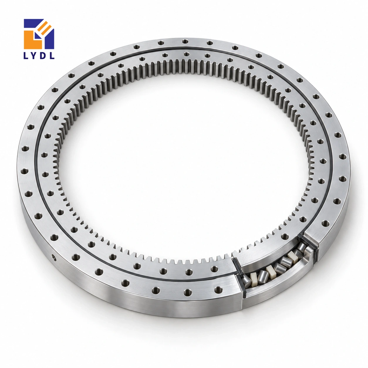
The XSI140414 internally geared slewing bearing is a crossed roller reference with a 325 mm bore and 484 mm outside diameter. Its 56 mm reference height and module 5, 67-tooth internal gear place the drive within the ring perimeter.
XSI140414: LYDL table; original height from Catalogue 404, pp. 84–85. Ordered execution requires drawing agreement.
XSI specification tables · Family technical reference
| Bore (mm) | Outside (mm) | Height H (mm) | Mass ≈ (kg) |
|---|---|---|---|
| 325 | 484 | 56 | 31 |
| Outer PCD La (mm) | Inner PCD Li (mm) | Outer holes na | Inner holes ni |
|---|---|---|---|
| 460 | 375 | 24 | 24 |
| Pitch d0 (mm) | Module m (mm) | Teeth z |
|---|---|---|
| 335 | 5 | 67 |
XSA140414 uses external teeth and has a different bore, outside diameter and fixing layout. Moving the pinion inside the ring therefore requires a complete assembly review, not just relocating the same bracket. Reserve central space for the internal mesh, adjustment and service access. Decide which ring is fixed in the machine and identify how the pinion reaction returns to that support, while keeping the moving platform load path clear.
The listed fixing circles are 460 mm and 375 mm, with twenty-four positions per ring. Confirm pilot steps and detailed screw geometry for the supplied drawing, especially around the inner-drive mounting.
Label the fixed ring, rotating ring, pinion support and platform on the assembly section. This makes the drive reaction and the platform force path visible without relying on a product photograph. Identify how the pinion centre is adjusted and which locating surfaces remain undisturbed during that adjustment. Check whether the drive can be serviced while the platform stays supported.
At the centre opening, add the real cable connector envelope and its bend or twist allowance. A nominal bore clearance can disappear when the pinion bracket and inner screws are drawn in their installed positions. For an antenna layout, specify the point at which pointing error or displacement is judged and the environmental conditions used for that assessment. The ring, bracket, transmission and structure each contribute to the output behaviour.
Requesting a bearing with an undefined accuracy label cannot establish that system result. The original XSI140414-N reference is useful for geometry comparison, but it does not certify the supplied LYDL execution or the completed antenna. Agree component acceptance and equipment commissioning as separate activities, using consistent drawings and stated test conditions. For a compact antenna head, check where each connector sits at the extremes of travel, including the bend required to unplug it.
Distinguish this temporary service envelope from the normal cable route. A pinion bracket may need a removable panel even when the motor fits inside the ring perimeter. Making these constraints visible early helps preserve the intended compact layout without sacrificing access to the actual connection.
The XSI140414 gear row describes internal teeth with module 5 and 67 teeth. Their product is 335 mm, matching the listed nominal pitch diameter. That arithmetic checks the relationship between three entries; it does not calculate a permissible tooth force. The physical outside diameter is 484 mm and the bore is 325 mm, so neither should be replaced by the pitch-circle value in a clearance drawing. Overall height H is 56 mm. Locate the gear face and the two mounting planes from the offered section before positioning a pinion. The tooth form, engagement, quality requirement and supplied material execution remain separate specification items. Keeping these definitions distinct prevents a correct transmission number from being used as the wrong housing dimension.
Moving the mesh inside the ring can help organise a perimeter that must remain clear for tooling. It also places the pinion, shaft and bracket in the central region. Sketch that entire assembly inside the nominal 325 mm bore arrangement, including the path used to install and remove it. A large-looking opening can be occupied quickly by a transmission and its access needs.
Identify which covers move with the platform and which remain fixed. Show how the mesh can be observed or adjusted without disturbing unrelated equipment. Internal placement does not create a documented ingress-protection rating or remove the need to describe particles and cleaning exposure. The offered protection needs review against the real environment.
The internal gear lists module 5 and a 335 mm nominal pitch circle. Specify the proposed pinion and reduction before interpreting the 67-tooth count as a machine motion relationship. The pinion support and adjustment also influence how the mesh behaves under load. Show those parts with their actual connection to the base.
For an orienting fixture, define the positions, approach direction and settling condition that matter. Identify the datum at which a result is measured. A requirement at a workpiece feature includes the nest, support, joints and drive as well as the ring. Request the applicable supplied execution and an agreed observation method rather than assigning a precision or backlash value from nominal gear dimensions.
Both rings list twenty-four positions, yet their circles are different: 460 mm outside and 375 mm inside. Keep them as distinct features in the base and rotating flange drawings. Add the actual screw seats, engagement and locating shoulders from the offered section. Check whether the internal pinion bracket blocks access to the inner connection.
Show the real flange backing beneath each pattern, including any opening for the motor or central services. Describe the assembly sequence and geometry-check condition. A pattern that fits in plan still needs sufficient access and an assessed supporting structure. Do not use the ring or its screws to resolve an uncertain pilot or force a distorted flange into place.
XSA140414 retains the same nominal 56 mm height but uses external gearing, a 344 mm bore and a 503.3 mm outside envelope. Its attachment counts and circles also differ. The XSI reference here is therefore an alternative layout concept, not an interchangeable orientation of the same ring.
If the motivation is to clear the outside of a machine, compare the complete internal drive against the space and services at the centre. Include maintenance movements and the route by which drive reactions enter the base. Then request the drawing for the preferred offered configuration. Record that identity with the inspection scope and operating cases so future spare enquiries preserve the actual arrangement.
XSI140544 enlarges the opening from 325 to 444 mm and the outside envelope from 484 to 614 mm while retaining 56 mm H. It changes the internal gear from module 5 and 67 teeth to module 6 and 76 teeth. Thirty-two positions per ring replace the twenty-four listed here.
On a compact orienter, draw the internal bracket and services for both candidates. Determine whether a larger central region is needed for operation, assembly or maintenance. Each question can produce a different layout preference. The retained working-height allowance does not preserve the pinion interface or attachment patterns. Obtain the individual offered section and review the fixture duty before deciding which nominal reference to pursue.
A compact antenna platform is an illustrative design study. Evaluate cable twist, wind moments and the full pinion housing envelope alongside the required pointing behaviour.

Agree inspection of the internal teeth and mounting datums before ordering. Protection inside the bore should prevent loose parts striking tooth flanks during transport.

The reference is 325 × 484 × 56 mm, with approximate listed mass 31 kg. Confirm the actual delivered execution with LYDL.
No. XSI140414 lists 325 mm bore, while the external-gear XSA140414 reference lists 344 mm. Other interfaces also differ.
The internal gear reference gives module 5, 67 teeth and a 335 mm pitch diameter.
Twenty-four positions per ring are listed, on 460 mm and 375 mm fixing circles. Check their full angular and screw details.
The pinion, bracket and adjustment space occupy part of it. Include these components when reviewing clearance for cables or a rotary union.
Perimeter drive: XSA series. Separate-drive reference: XSU range.
Send the internal-pinion section, fixed-ring arrangement and central service routing for XSI140414.