

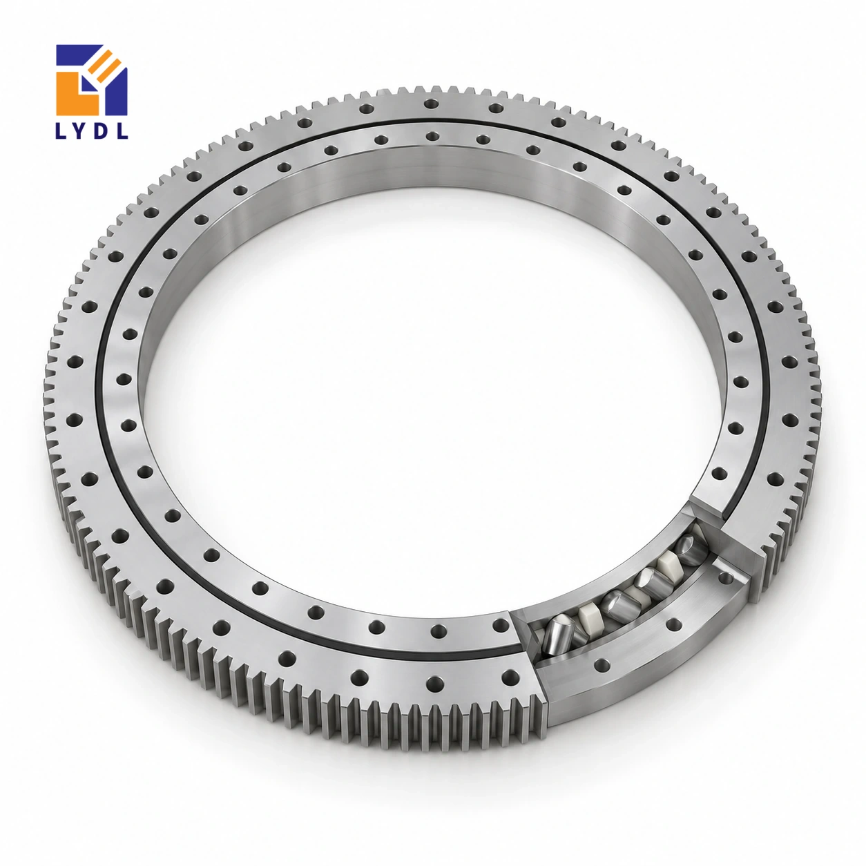
The XSA141094 externally geared crossed roller reference is the largest XSA size in this request. Its nominal envelope is 1024 × 1198.1 × 56 mm, with a module 8, 148-tooth gear and an 1184 mm pitch diameter.
XSA141094 reference dimensions: Catalogue 404, pp. 82–83; LYDL gear listing. Confirm the actual supply drawing.
XSA specification tables · Family technical reference
| Bore (mm) | Outside (mm) | Height H (mm) | Mass ≈ (kg) |
|---|---|---|---|
| 1024 | 1198.1 | 56 | 91 |
| Outer PCD La (mm) | Inner PCD Li (mm) | Outer holes na | Inner holes ni |
|---|---|---|---|
| 1135 | 1048 | 44 | 48 |
| Pitch d0 (mm) | Module m (mm) | Teeth z |
|---|---|---|
| 1184 | 8 | 148 |
A bore exceeding one metre may suit a platform around substantial central equipment, but the support is still an annular structure. Review plate sections, access cutouts and peripheral bracket loads around the 1135 mm outer and 1048 mm inner fixing circles. The 56 mm reference height is not a recommendation for the thickness of either machine flange. Assess the upper platform and base together under eccentric and horizontal forces.
The original reference lists forty-four outer and forty-eight inner fixing positions. Establish a lifting and tightening sequence that preserves access around the central equipment and the external drive.
Trace the loads through the annular upper platform to the bearing connection and from the lower connection into the base. Mark local ribs, pockets and service openings rather than treating either flange as an uninterrupted solid disc. A central opening intended for large equipment often introduces brackets whose forces bypass or locally enter the annulus. Identify each route.
The reference height describes the ring, while the surrounding flange needs its own structural assessment. Include horizontal forces at the actual equipment height and determine the permitted eccentric payload states. For an antenna platform, describe operating and idle environmental cases separately and show cable-management reactions. The large opening also needs a service plan: inner screw access, pinion withdrawal, lifting sequence and protection while the platform is supported.
Confirm that those operations can be carried out with the central equipment in its documented state. Reference dimensions help establish initial feasibility; the accepted LYDL execution and the complete machine assessment determine the final proposal.
The XSA141094 gear row describes external teeth with module 8 and 148 teeth. Their product is 1184 mm, matching the listed nominal pitch diameter. That arithmetic checks the relationship between three entries; it does not calculate a permissible tooth force. The physical outside diameter is 1198.1 mm and the bore is 1024 mm, so neither should be replaced by the pitch-circle value in a clearance drawing. Overall height H is 56 mm. Locate the gear face and the two mounting planes from the offered section before positioning a pinion. The tooth form, engagement, quality requirement and supplied material execution remain separate specification items. Keeping these definitions distinct prevents a correct transmission number from being used as the wrong housing dimension.
The 1024 mm bore can be considered around a substantial stationary process assembly, but its collars, connectors and service motions must be drawn too. Add the rotating deck and external pinion on a common section. Identify how the central assembly is installed and whether it can later be removed without disturbing the ring.
At the perimeter, the nominal 1198.1 mm tooth envelope is only part of the equipment footprint. The pinion bracket, motor, guard and tools need additional space. Check workshop and transport routes for the complete assembly as well as the loose component. Layout decisions made from a bare-ring outline can miss these practical constraints.
Provide payload locations, fixture masses and process forces for every permitted operating configuration. Include the height of applied forces and partially occupied states. The largest designation in this requested group does not establish that it covers an unspecified load or moment. The approximate 91 kg component mass is a handling value, not a permissible workpiece mass.
For movement, give angular travel, acceleration, reversals and duty timing. Show any separate restraint used during processing or parking. Define the required installed behaviour at the actual working datum. The deck, frame connections and transmission contribute to that result, so the proposed bearing execution needs review within the complete machine.
The gear is listed as module 8 with a nominal pitch diameter of 1184 mm. Identify the intended pinion, its shaft support and the method of adjustment. Include the tooth-face position from the offered section and the guard's service opening. Do not infer allowable torque or a tooth quality class from size and tooth count.
If an existing drive is to be retained, compare its actual geometry and motion relationship with this ring. A common module across several XSA sizes does not preserve output movement per pinion revolution. State whether positions are approached from one direction or both and specify where the required result is observed. This gives the transmission review a concrete operating target.
The outer pattern has forty-four listed positions on a 1135 mm circle, while the inner has forty-eight on a 1048 mm circle. Keep the counts tied to their respective rings on drawings, inspection sheets and assembly instructions. Confirm actual screw form, engagement, seats and locating details with the supply drawing.
Show the supporting annuli as manufactured, including joints, pockets and access openings. Check tool access around the installed central equipment and drive. Define the seating inspection condition and the accepted fastening sequence. A large flange can still contain a locally unsupported sector, and neither its apparent size nor the total fastener count establishes an adequate connection on its own.
Attach the mating parts, operating schedule and requested evidence to the enquiry. Resolve the offered LYDL execution against the original-reference geometry before machining. Identify the component on receipt and keep the drawing revision with inspection information.
Plan handling and storage to protect machined faces and teeth, using approved provisions for the supplied ring. Record the installed configuration and test condition at commissioning, separately from component checks. Describe the actual contamination and cleaning exposure. Later changes to the central process module, platform overhang or drive should be assessed against that accepted record, giving spare orders a precise technical basis.
XSI141094 is a useful alternative drive concept at 984 × 1164 × 56 mm, with module 8 and 125 internal teeth. XSA141094 has 1024 × 1198.1 × 56 mm and 148 external teeth. Its forty-four outer/forty-eight inner connection also differs from the forty-eight positions per ring of XSI.
The decision depends on where transmission and maintenance space are available. Show the large central process body with the pinion in each concept, plus the enclosure around the outside. Common height and module do not establish compatible mating parts. Choose a complete layout and request its offered drawing and application assessment instead of treating the drive location as a reversible option on one assembly.
A large antenna azimuth platform is an illustrative layout. Wind forces, pointing duty, cable management and environmental protection require application data; the size alone does not establish suitability.

Agree transport support, receiving checks and measurement conditions before shipment. Keep wooden supports, straps and loose accessories clear of gear flanks, seals and machined datums.

No. The reference bore is 1024 mm. The model number is not a substitute for the actual dimension table.
Both list module 8, but XSA141094 has 148 teeth and an 1184 mm pitch diameter rather than 129 teeth and 1032 mm.
Forty-four outside and forty-eight inside, located on 1135 mm and 1048 mm circles in the original reference.
No. It describes the bearing reference height. Supporting-flange thickness must be designed for the actual structure and loading.
No. Supply environmental loads, operating motion, pointing requirements and protection details for a complete engineering assessment.
Internal mesh: XSI series. Gearless alternative: XSU range.
Request XSA141094 with a central-equipment section, load cases and a documented installation access plan.