

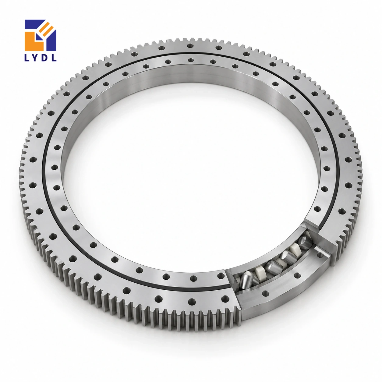
XSA140944 is an external gear cross roller reference measuring 874 × 1046.1 × 56 mm. Module 8 and 129 teeth define the listed transmission, while the mounting system uses forty outer and forty-four inner fixing positions.
XSA140944 reference dimensions: Catalogue 404, pp. 82–83; LYDL gear listing. Confirm the actual supply drawing.
XSA specification tables · Family technical reference
| Bore (mm) | Outside (mm) | Height H (mm) | Mass ≈ (kg) |
|---|---|---|---|
| 874 | 1046.1 | 56 | 77 |
| Outer PCD La (mm) | Inner PCD Li (mm) | Outer holes na | Inner holes ni |
|---|---|---|---|
| 985 | 898 | 40 | 44 |
| Pitch d0 (mm) | Module m (mm) | Teeth z |
|---|---|---|
| 1032 | 8 | 129 |
The original reference mass is approximately 77 kg, before any machine plate is attached. Define how the ring reaches the assembly station and how the final seating faces will be inspected. A fabricated base can change shape after welding, machining or attachment of peripheral equipment. Check its completed support condition before mounting the ring, then compare rotation behaviour after fastening to identify a distorted interface early.
The nominal fixing circles are 985 mm outside and 898 mm inside. Confirm access to all forty and forty-four positions, and provide a practical removal path for the external pinion and guard.
A fabricated base may be held differently during machining, inspection and machine assembly. Record those supporting conditions where they affect the seating geometry. Check the final flange after attachments that can introduce distortion are completed. Plan a comparison of running behaviour at defined assembly stages, with interference checks around the external drive.
Avoid using additional motor torque to conceal an unexpected increase in resistance. Determine where the forty-four-position inner connection is reached once the tooling frame is attached. An access plan should show the actual driver and removal path, not just a visible screw centre. For handling, establish the complete lifted configuration and use approved support points, keeping the exposed gear protected.
Define receiving checks separately from the installed machine test and identify the accepted drawing revision in both records. This gives later service work a useful baseline and helps distinguish a support change from a different delivered execution. Give service personnel a drawing of the permitted access configuration, showing which guards and brackets may be removed independently. Record the mesh-setting method used at commissioning and the measurement condition at the output.
If a later repair changes a bracket or fabrication, reassess that baseline before blaming the ring for changed motion. The useful maintenance reference is the complete installed arrangement, with its configuration and observations documented.
The XSA140944 gear row describes external teeth with module 8 and 129 teeth. Their product is 1032 mm, matching the listed nominal pitch diameter. That arithmetic checks the relationship between three entries; it does not calculate a permissible tooth force. The physical outside diameter is 1046.1 mm and the bore is 874 mm, so neither should be replaced by the pitch-circle value in a clearance drawing. Overall height H is 56 mm. Locate the gear face and the two mounting planes from the offered section before positioning a pinion. The tooth form, engagement, quality requirement and supplied material execution remain separate specification items. Keeping these definitions distinct prevents a correct transmission number from being used as the wrong housing dimension.
The nominal ring has an 874 mm opening, 1046.1 mm outside diameter and 56 mm overall height. Place those dimensions in the complete equipment stack, including the supporting base, rotating deck and adapters. A low ring section does not determine the stiffness or overall height of the assembled table.
Draw any fixed central equipment with its service motions. Establish the route for installing and removing it after the deck is in place. Check inner fastener access and the temporary support needed during a bearing replacement. These practical constraints may decide the preferred layout before a supplier is asked to assess the operating load.
For a large table, list where fixtures, workpieces and process tools act rather than presenting only their summed weight. Include empty and partially loaded configurations. A lighter part at a larger radius or greater height can create an important case that differs from the heaviest centred load.
Describe angular movement, normal reversal and dwell with the moving mass distribution. If a process restraint carries load while stopped, show its connection to the base and table. Define the installed result at a useful working point. Any displacement there includes contributions from the deck, joints, drive and bearing arrangement, so a component designation cannot provide the complete answer.
Module 8 and 129 teeth give the listed 1032 mm nominal pitch diameter. Position the actual pinion support and enclosure beyond the ring envelope and check their removal route. Establish tooth-face location from the offered section rather than deriving it from total height. Agree the proposed mating geometry and engagement checks.
Identify the required drive result under the actual operating sequence. A shared module with XSA140844 does not preserve the same tooth-count relationship, and it does not establish permissible tooth force. Keep the motion requirement, pinion details and supplied execution linked in the technical proposal so the drive can be reviewed as an assembly.
The 985 mm outer fixing circle and 898 mm inner circle use different listed counts. Give each pattern its own feature identity in the mating drawings and inspection plan. Add the actual seats, screw engagement and locating shoulders once the offered execution is agreed. Check angular orientation against the drive and central services.
Review backing around the circumference, including access windows, local recesses and frame joints. Specify the condition in which seating geometry is measured and plan a practical assembly sequence. The ring should not be used to pull an uncertain support into alignment. Tool access, prepared interfaces and a defined fastening method are all needed to turn the nominal pattern into a workable connection.
The approximate 77 kg listed mass assists planning for receiving and handling the component. Request suitable handling provisions and shipment protection for the actual supply. Keep loose table hardware away from the machined faces and external teeth. Preserve identity and the accepted drawing revision after unpacking.
Agree component inspection separately from the installed table test. For the latter, record payload configuration, observation datum and approach direction. Include contamination, cleaning and idle periods in the enquiry. A documented configuration gives future spares a clear basis; the generic inspection montage cannot substitute for ordered-model evidence or certify this table's performance.
XSA141094 provides a 1024 mm opening and 1198.1 mm outside envelope, compared with 874 mm and 1046.1 mm here. Both list 56 mm height and module 8. The larger ring has 148 teeth rather than 129, and forty-four outer/forty-eight inner positions rather than forty/forty-four.
For a table with a fixed working plane, compare the complete deck and pinion sections rather than preserving only H. Show the central equipment's removal path and the frame beneath the wider patterns. A larger opening may solve access while creating changes in support, ratio and handling. Request the individual proposed execution with the payload locations and process schedule attached before making a final selection.
A handling turntable with an overhanging tooling frame is one study example. Include side forces at the frame height, emergency stopping and uneven payload positions in the review.

Specify dimensional and functional acceptance with the supplied drawing revision. Discuss a supported shipping base and edge protection that do not use the gear perimeter as a lifting surface.

The cited envelope is 874 mm bore, 1046.1 mm outside diameter and 56 mm height, with approximate reference mass 77 kg.
The external gear reference is 1032 mm at module 8 with 129 teeth.
The original data list forty outer positions and forty-four inner positions on 985 mm and 898 mm circles.
Inspect the completed machined seating after fabrication operations that may distort it, before the bearing connection is tightened.
Use an approved handling method for the supplied assembly. Do not assume the exposed gear teeth are suitable lifting attachment points.
Internal mesh: XSI series. Gearless alternative: XSU range.
For XSA140944, attach the handling plan, completed-base section and worst tooling overhang.