

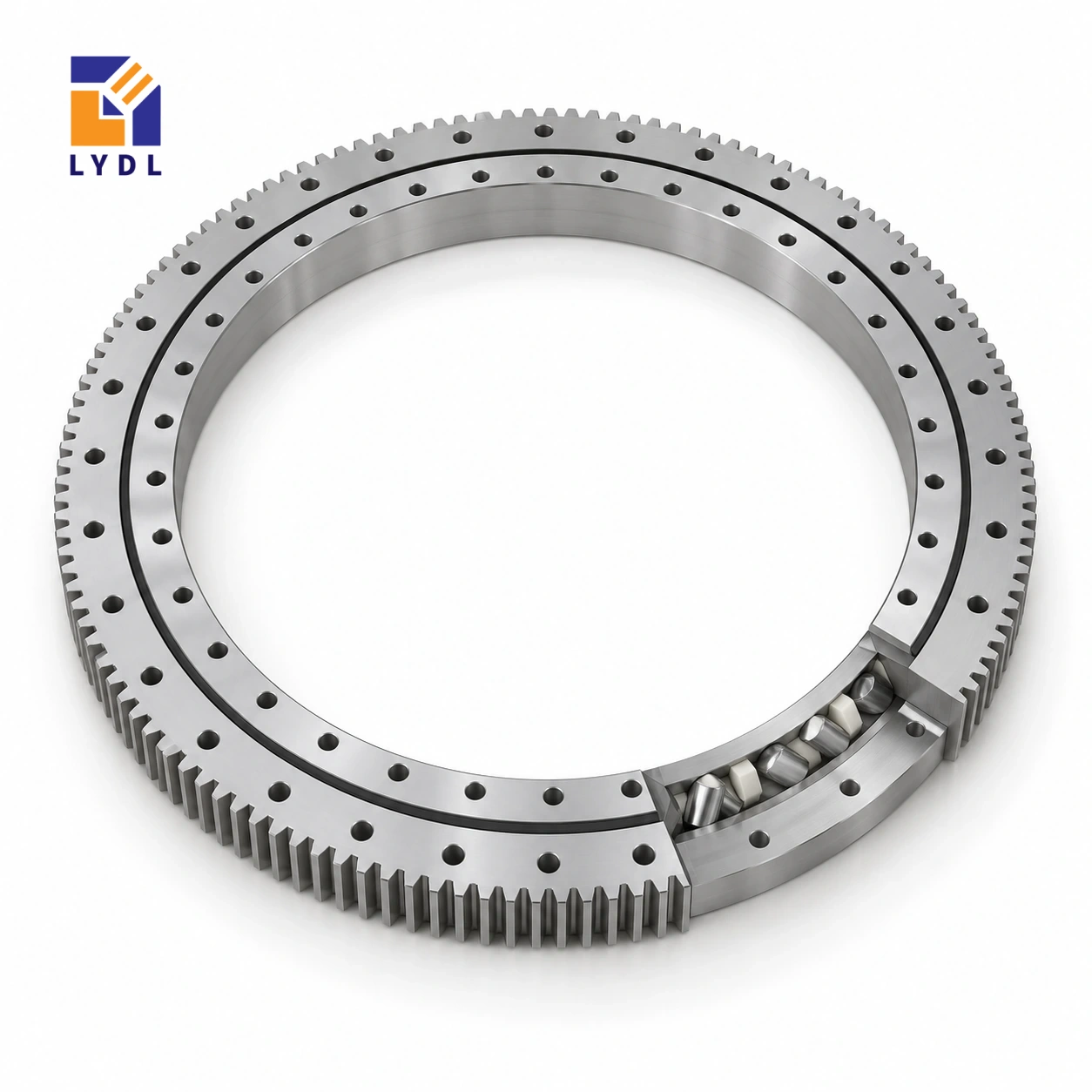
The XSA140844 externally geared reference has a 774 mm bore, 950.1 mm outside diameter and 56 mm height. Its crossed roller arrangement is paired with a module 8, 117-tooth gear listing, introducing a gear-module change from XSA140744.
XSA140844 reference dimensions: Catalogue 404, pp. 82–83; LYDL gear listing. Confirm the actual supply drawing.
XSA specification tables · Family technical reference
| Bore (mm) | Outside (mm) | Height H (mm) | Mass ≈ (kg) |
|---|---|---|---|
| 774 | 950.1 | 56 | 71 |
| Outer PCD La (mm) | Inner PCD Li (mm) | Outer holes na | Inner holes ni |
|---|---|---|---|
| 885 | 798 | 36 | 40 |
| Pitch d0 (mm) | Module m (mm) | Teeth z |
|---|---|---|
| 936 | 8 | 117 |
Although the reference diameter increases, the tooth count drops from 138 to 117 because the listed module changes from 6 to 8. Tooth count alone therefore cannot serve as a bearing-size or load-capacity ranking. Specify the new pinion, engagement geometry and bracket stiffness, and check the complete drive ratio before carrying over a motor setting. The platform and bolted joint still require their own load review.
The reference has thirty-six outer positions on an 885 mm circle and forty inner positions on a 798 mm circle. Keep access to the external mesh and confirmed lubrication points in the finished enclosure.
Compare the physical space occupied by the proposed module 8 pinion, its shaft and supporting bearings with the previous drive arrangement. A changed pinion can alter bracket reactions, motor position and guard dimensions even when the basic machine concept remains the same. Identify the complete reduction ratio and revise control assumptions from that transmission, not from ring tooth count alone. State the required operating torque history and leave material, treatment and quality requirements to the agreed gear specification.
For a positioner, map imbalance over the permitted workpiece angles and identify any external force from clamps or process equipment. Show how the electrical return and protective covers move with that fixture. Describe the contamination path to the external mesh and the maintenance access needed to inspect it. These are practical equipment requirements; the page does not imply that a module change establishes a higher permissible load, improved accuracy or immunity to welding exposure.
The final supply drawing should identify the execution used for the assessment.
The XSA140844 gear row describes external teeth with module 8 and 117 teeth. Their product is 936 mm, matching the listed nominal pitch diameter. That arithmetic checks the relationship between three entries; it does not calculate a permissible tooth force. The physical outside diameter is 950.1 mm and the bore is 774 mm, so neither should be replaced by the pitch-circle value in a clearance drawing. Overall height H is 56 mm. Locate the gear face and the two mounting planes from the offered section before positioning a pinion. The tooth form, engagement, quality requirement and supplied material execution remain separate specification items. Keeping these definitions distinct prevents a correct transmission number from being used as the wrong housing dimension.
The 56 mm nominal height is shared with smaller XSA references, but this row changes the gear to module 8 with 117 teeth. XSA140744 uses module 6 and 138 teeth. Keeping the same axial package does not preserve a mating pinion or transmission ratio. Show the proposed pair explicitly and review the support and adjustment that locate it.
The present pitch circle is 936 mm and the outside tooth envelope is 950.1 mm. Include the peripheral guard and motor beyond those ring dimensions. Check whether an existing machine frame permits the new drive centre and maintenance route. A comparison based only on height can conceal changes in nearly every radial interface.
Draw the fixed equipment through the 774 mm opening, with collars, service outlets and removable modules. Add the rotating deck and its tooling through the full intended motion. Identify any stationary attachment that carries process forces directly to the base, separately from forces passing through the ring.
Check assembly access to the inner connection before the central equipment is installed. Determine whether a module can be removed without lifting the entire deck and where tools can be placed. The nominal bore describes the ring, whereas useful service space depends on the combined arrangement. Resolve those routes while the layout remains adjustable rather than adding structural openings late in manufacture.
Show the tooling and payload at their actual radii and heights. Include partially occupied states and forces during processing. A wide deck can display movement at its working edge from several sources, including plate bending, joints, transmission and the bearing arrangement. Define the observation datum and operating condition before requesting a numerical result.
The outer attachment lists thirty-six positions on an 885 mm circle and the inner forty on a 798 mm circle. Overlay those patterns on the real backing sections. Include pockets and bracket connections, and obtain the offered screw and locating details. A visually broad flange or a high fastener count is not a substitute for assessing the complete joint.
Plan receipt and handling using the approximately 71 kg listed component mass and the actual delivered package. Request handling information for the supplied execution rather than lifting from an unapproved local feature. Protect the annular seating and tooth perimeter from loose hardware and uneven support.
Before fastening, verify the prepared mating surfaces against the agreed drawing and assembly method. Check that the motor bracket, guards and central services leave access to both patterns. Record the support condition for receiving observations and distinguish them from loaded machine tests. This gives the installation team a defined basis for identifying an interface problem without improvising at the ring.
Provide the equipment layout, operating schedule and required inspection information with the enquiry. Original-reference geometry helps identify this XSA size, while the accepted LYDL drawing defines the ordered execution. Confirm the actual tooth, sealing and service arrangements in that record.
For commissioning, retain the tooling and drive configuration used for the baseline observation. Describe the environment and storage interval when discussing protection. The shared photographs illustrate an external-gear family and general applications; they cannot guarantee a specific accuracy, load or completed-machine result. Future spare requests should refer to the accepted configuration and its revision.
The next requested XSA size, XSA140944, has an 874 mm bore and 1046.1 mm outside diameter at 56 mm H. Module 8 remains, but the tooth count increases from 117 to 129. The outer/inner attachment counts change from thirty-six/forty to forty/forty-four.
If a fixed process body motivates the move, compare its service envelope within both openings. Check the added platform span, frame backing and drive ratio explicitly. A common module may leave some transmission concepts familiar, while the actual mating geometry and operating assessment remain specific to each candidate. Obtain the offered section for the selected layout and retain the process duty in its technical record.
A large welding-positioner table is an illustrative engineering case. Include workpiece imbalance and a dedicated electrical return arrangement, and review contamination at the external tooth mesh.

Request gear inspection appropriate to the agreed pinion and datum checks for the flange. Protective packing must avoid concentrating handling forces on the exposed teeth.

The listed module changes from 6 to 8 while the pitch diameter increases. Tooth count should be read with module and pitch diameter.
The reference lists module 8, 117 external teeth and a 936 mm pitch diameter.
The original reference gives a 774 mm bore and 56 mm height, within a 950.1 mm outside diameter.
No automatic torque claim follows. The actual gear execution, engagement, support and duty determine the applicable limit.
Compare thirty-six outer positions on 885 mm and forty inner positions on 798 mm, including their angular orientation and detailed screw geometry.
Internal mesh: XSI series. Gearless alternative: XSU range.
Send the revised gear ratio, module 8 pinion and workpiece orientation cases with XSA140844.