

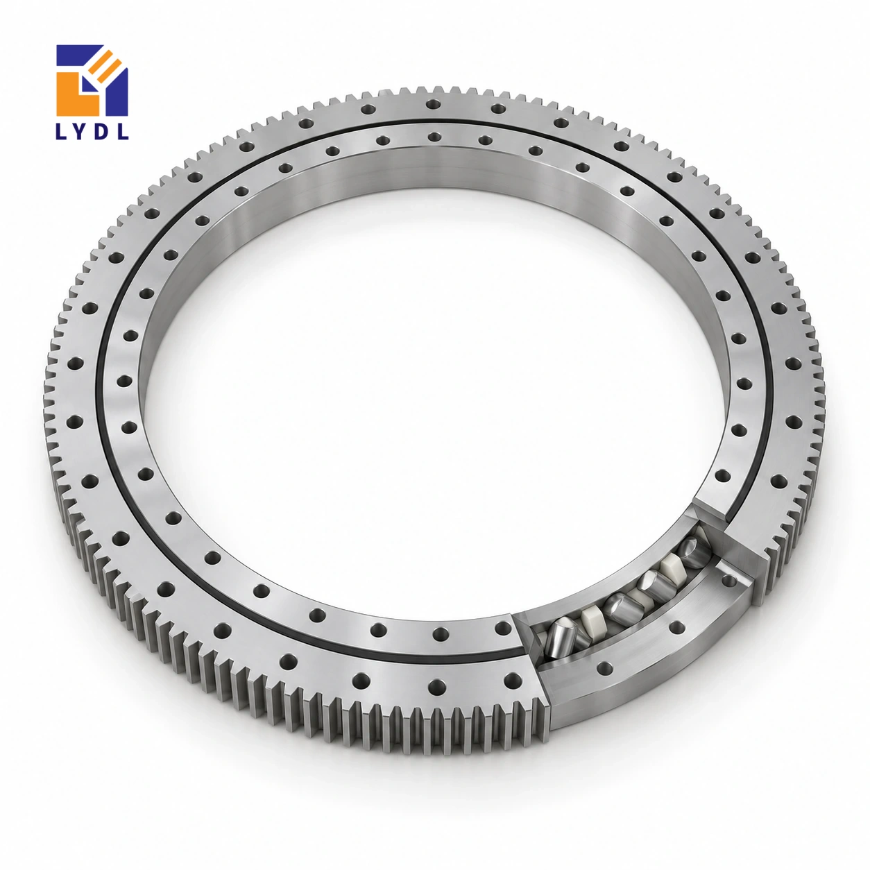
The XSA140414 externally geared slewing bearing uses a crossed roller reference arrangement with a 344 mm bore and 503.3 mm outside diameter. Its 56 mm reference height and module 5 external gear provide a starting package for a perimeter-driven rotary support.
XSA140414 reference dimensions: Catalogue 404, pp. 82–83; LYDL gear listing. Confirm the actual supply drawing.
XSA specification tables · Family technical reference
| Bore (mm) | Outside (mm) | Height H (mm) | Mass ≈ (kg) |
|---|---|---|---|
| 344 | 503.3 | 56 | 32 |
| Outer PCD La (mm) | Inner PCD Li (mm) | Outer holes na | Inner holes ni |
|---|---|---|---|
| 455 | 368 | 20 | 24 |
| Pitch d0 (mm) | Module m (mm) | Teeth z |
|---|---|---|
| 495 | 5 | 99 |
The original reference lists twenty outer fixing positions and twenty-four inner positions. Treat the patterns independently when laying out the mating plates; a single repeated-hole instruction would not describe both rings correctly. The outer and inner circles are 455 mm and 368 mm. Establish their angular relationship from the approved drawing, especially if the machine uses dowels, limited-access screws or a pre-existing attachment plate.
Locate the pinion and its adjustment travel outside the 503.3 mm bearing envelope. Confirm the centring and gear specification for the supplied execution rather than transferring reference tolerances into the purchase order without review.
Give the outer and inner connection patterns separate drawing identifiers. The twenty-position side and the twenty-four-position side should not share a generic hole-count note. Add any required angular orientation between them, using the accepted bearing drawing to establish the actual relationship. If dowels are used by the equipment design, locate them independently of the clearance holes.
Review the tool route for both connections before placing the external pinion bracket. Check whether the fixture faceplate can be removed without dismantling a correctly adjusted drive. For a welding station, show the current return, clamps and guard on the equipment layout, so they do not become late obstructions near the bearing screws. Describe the workpiece orientation that creates the largest offset, rather than assuming a centred loading position governs operation.
The original catalogue reference supplies a comparison geometry; the LYDL proposal should state the delivered execution and acceptance requirements. Keep dimensional identification separate from any optional application test performed on the finished positioner.
The XSA140414 gear row describes external teeth with module 5 and 99 teeth. Their product is 495 mm, matching the listed nominal pitch diameter. That arithmetic checks the relationship between three entries; it does not calculate a permissible tooth force. The physical outside diameter is 503.3 mm and the bore is 344 mm, so neither should be replaced by the pitch-circle value in a clearance drawing. Overall height H is 56 mm. Locate the gear face and the two mounting planes from the offered section before positioning a pinion. The tooth form, engagement, quality requirement and supplied material execution remain separate specification items. Keeping these definitions distinct prevents a correct transmission number from being used as the wrong housing dimension.
The outer ring has twenty listed fixing positions and the inner ring has twenty-four. Treat them as separate interfaces in the CAD model and manufacturing drawings. Copying one count to both rings would lose an important distinction even though both patterns belong to the same bearing assembly. Show the 455 mm and 368 mm circles with their correct ring identities.
Add the actual locating and screw details from the offered execution. Confirm the angular relationship required by the machine and check every tool path with the drive bracket present. An adapter needs its own defined connection on each side; a generic drilled disc does not establish location, engagement or adequate backing. Resolve those features before releasing a set of mating plates.
For a fixture changed between jobs, show the complete removal operation. Include the lifting or support arrangement for the fixture, the route past the external pinion and the tools used to release its connections. The guard may need to open farther for maintenance than its operating envelope suggests. Plan where removed parts are placed without contacting the ring's machined interfaces.
The 344 mm bore and 503.3 mm outside diameter describe the ring envelope. The module 5, 99-tooth gear introduces a drive interface at a 495 mm pitch circle. Draw the actual pinion support and adjustment rather than reserving only a motor-sized box. Identify which fixture changes alter the moving inertia, payload offset or process force and therefore require application review.
XA160407 shares the listed 503.3 mm outside diameter and module 5, 99-tooth gear, but its nominal bore is 335 mm and overall height is 50 mm. XSA140414 is listed at 344 mm bore and 56 mm height. The attachment data also differs. A shared gear geometry is therefore a useful comparison point, not evidence that the complete assemblies interchange.
Overlay the sections if an existing pinion is to be retained. Check tooth position, flange stack and connection features individually. Ask for the actual proposed drawing and identify the dimensions fixed by the machine. This turns a plausible comparison into a reviewable interface study without claiming compatibility from a few matching numbers.
Describe the fixture, part and clamps at their real locations. Include loading actions and process forces during dwell, as well as the rotation schedule. State which fixture variants are allowed and how their centres of gravity differ. The approximately 32 kg listed ring mass helps plan component handling but provides no approved fixture capacity.
Choose the installed datum at which behaviour matters and specify a repeatable observation condition. The plate, joints, transmission and bearing arrangement all affect that result. Keep component receiving checks separate from the assembled-station test, with an agreed method for each. This avoids asking a nominal reference table to answer questions that depend on the entire equipment design.
Send the two mating patterns, pinion proposal and operating cases with the enquiry. Retain the accepted LYDL revision and any agreed inspection information in the purchase record. The original-reference dimensions are useful comparison evidence, while the supply drawing defines the offered component.
Explain the actual contamination and cleaning around the exposed gear. Discuss protection during storage and shipment, keeping loose fixture hardware away from the ring. The shared family image illustrates the external-gear arrangement; it does not prove this exact execution or its test results. A repeat order should reference the accepted configuration rather than relying on the appearance of a photograph.
Within XSA, the next requested opening is 474 mm in XSA140544, with 640.3 mm outside diameter. This row provides 344 mm and 503.3 mm respectively. Both list 56 mm H, but the transmission moves from module 5 and 99 teeth to module 6 and 105 teeth.
On a fixture that must be changed regularly, compare the access and removal route at each size. The larger ring's twenty-eight outer and thirty-two inner positions differ from the twenty and twenty-four here. Draw both mating patterns accurately before choosing an adapter. The shared height helps organise a section study but cannot preserve every drive and connection feature or establish equivalent equipment performance.
A welding-positioner faceplate is one representative use study. Check clamp reactions and workpiece imbalance at each orientation, and design shielding around the exposed gear mesh.

Discuss gear geometry and locating-face checks against the accepted drawing. Protective packaging should support the ring while keeping securing forces away from external tooth tips.

The original reference lists twenty outer positions and twenty-four inner positions. Confirm both patterns on the ordered drawing.
External module 5 teeth, 99 teeth total and a 495 mm pitch diameter are listed. Gear quality and backlash need their own requirements.
The cited original reference is 344 × 503.3 × 56 mm, with approximate mass 32 kg. LYDL supply is subject to its accepted drawing.
Do not assume that. Compare bore, locating features, both fixing circles and hole counts, then consider the added external drive.
It identifies the original catalogue reference. The requested LYDL base model remains XSA140414, with supplied execution confirmed in the order documents.
Internal mesh: XSI series. Gearless alternative: XSU range.
Request XSA140414 with separate inner and outer flange drawings plus the module 5 pinion specification.