

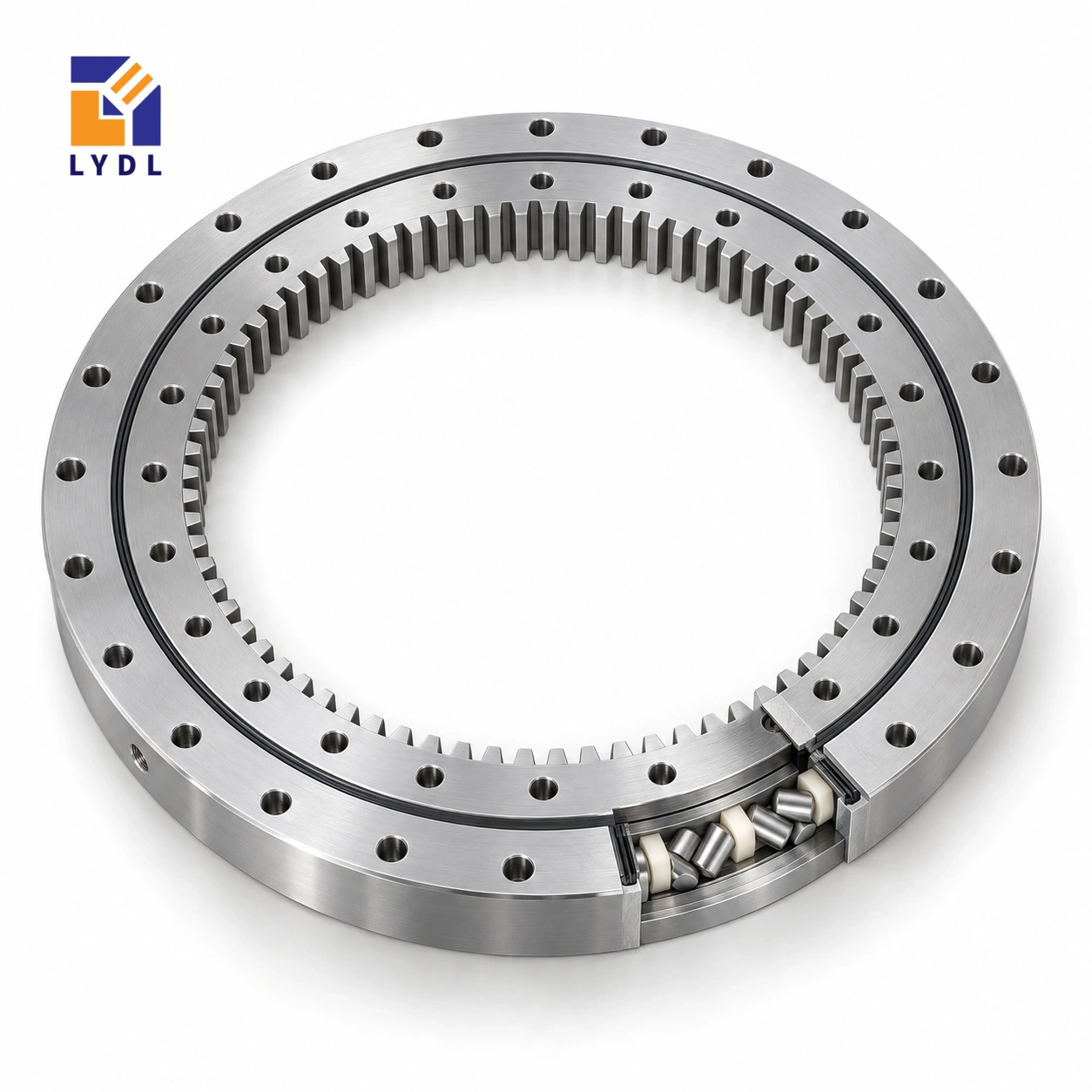
The XI160489 internally geared bearing is a LYDL cross roller listing with a 384 × 562 × 45 mm envelope. Module 6 and 66 teeth identify its listed transmission geometry; the forty-position fixing patterns define a separate mounting interface.
XI160489: nominal LYDL listing. INA interchange unverified. Supplied execution requires an agreed drawing.
XI specification tables · Family technical reference
| Bore (mm) | Outside (mm) | Height H (mm) | Mass ≈ (kg) |
|---|---|---|---|
| 384 | 562 | 45 | 35 |
| Outer PCD La (mm) | Inner PCD Li (mm) | Outer holes na | Inner holes ni | Hole dB (mm) | Secondary h (mm) |
|---|---|---|---|---|---|
| 538 | 440 | 40 | 40 | 14 | 40 |
| Pitch d0 (mm) | Module m (mm) | Teeth z | Width b (mm) |
|---|---|---|---|
| 396 | 6 | 66 | 40 |
Moving from a module 4 reference to this module 6 listing requires more than shifting the pinion centre. Compare tooth geometry, pinion specification, face engagement and adjustment space. The listed gear width is 40 mm, while the bearing total height is 45 mm; these are different drawing features. This model is treated as an extended LYDL reference, with its exact execution subject to a confirmed drawing rather than an assumed original-brand equivalence.
Forty holes on each ring are listed on 538 mm and 440 mm circles. Check that the large fixing count leaves practical access beside the pinion bracket, sensors and central service equipment.
When proposing a module 6 drive, begin with a complete pinion drawing showing its supported shaft and the location of the engaged face. A pinion cantilevered beyond its support can deflect even if the ring itself is adequately mounted. Include the bracket section and its attachment to the fixed structure in the review. Specify how axial alignment is maintained after adjusting the mesh.
The available 40 mm reference gear width is a geometric entry, not permission to accept any contact position across that face. For a transfer platform, identify whether the arm retracts before rotation or changes radius while moving. The latter produces a different motion requirement from an otherwise identical platform that indexes only in a fixed configuration. Describe these sequences in plain steps with loads and positions.
Check access to the forty inner fixing locations after all drive equipment is present, including the space required to remove a damaged fastener. Keep any service openings on the structural drawing. This allows the supporting flange to be evaluated in its manufactured form rather than as an ideal uninterrupted plate.
The XI160489 gear row describes internal teeth with module 6 and 66 teeth. Their product is 396 mm, matching the listed nominal pitch diameter. That arithmetic checks the relationship between three entries; it does not calculate a permissible tooth force. The physical outside diameter is 562 mm and the bore is 384 mm, so neither should be replaced by the pitch-circle value in a clearance drawing. Overall height H is 45 mm. Locate the gear face and the two mounting planes from the offered section before positioning a pinion. The tooth form, engagement, quality requirement and supplied material execution remain separate specification items. Keeping these definitions distinct prevents a correct transmission number from being used as the wrong housing dimension.
Consider a station that alternates between two processing angles. Record each travel segment, approach direction and dwell, then show the tooling mass relative to the rotary axis. Reversal repeatedly changes the drive reaction, and a heavy fixture close to the axis differs from a lighter tool extended outward. Give the moving mass distribution instead of only the total product weight.
State the required result at the workpiece after settling. If the process tolerates a direction-dependent offset, explain how it is managed; if it does not, make the bidirectional requirement explicit. The crossed-roller description identifies the bearing arrangement. It does not establish the positioning performance of the motor, reduction, internal mesh, flange and tool acting as one machine.
This row combines a 396 mm pitch diameter with 66 teeth. The internal mesh belongs within the 384 mm bore region, so show the pinion and its shaft support in a detailed section. Include the proposed tooth engagement and the height of the pinion relative to both ring mounting faces. The listed 40 mm gear width and 45 mm overall height describe different features.
There are forty listed attachment positions on each ring, with circles of 538 mm and 440 mm. Distinguish those patterns from the gear geometry when creating the flange drawings. More fasteners do not by themselves establish a stronger machine connection. Screw specification, engagement, tightening method and the stiffness of the mating structure remain part of the engineering review.
If an existing fixture provides the starting point, describe what is observed and under which condition. A useful record identifies the measurement location, load direction, approach and drive state. Compare a stationary unloaded observation with the defined operating case only when both tests are relevant. Avoid reducing a complex displacement complaint to an assumed bearing clearance.
Show joints between the ring and the tool, including adapters and bolted interfaces. Include the pinion bracket and encoder arrangement in the investigation. A change at any of these locations may appear as output movement. Ask for component checks and assembled-machine checks as separate items, with an agreed method for each. No numerical stiffness or runout specification is implied by the nominal dimensions on this page.
LYDL's row supplies the geometry used here, while a complete independent original-brand match remains unverified. Provide the actual mating parts and explain which dimensions must be preserved. A supplier proposal should identify its drawing revision and any deviations before the purchasing record treats it as a replacement.
Discuss debris protection around the internal mesh and the access needed for the offered service arrangement. Include the storage interval if the ring will wait before assembly. At delivery, verify identity and agreed dimensional features, and keep the records with the fixture documentation. A repeat purchase should reference the accepted execution as well as XI160489, particularly when the drive or tooling has changed since the initial installation.
XI180635 would provide a 504 mm bore within a 722 mm outside envelope and 54 mm height, compared with 384 × 562 × 45 mm here. Its module 8, 65-tooth internal gear also differs from this module 6, 66-tooth row. Similar tooth counts are not enough to preserve a pinion or drive ratio.
For the reversing fixture, retain the actual tool overhang and motion in the comparison. A larger ring does not change where the tool force acts unless the equipment is redesigned. Examine the base, bracket and attachment patterns on the complete sections. Use the geometry to identify candidates, then request review of the chosen supplied execution against the stated bidirectional output requirement.
A handling turntable with a shielded internal drive is a representative design study. Review a load that changes radius during transfer, including the drive reaction through the inner support.

Specify the tooth-contact and running checks needed for the agreed transmission. Protect the internal gear from hard loose objects and identify the ring separately from matching drive components.

The current LYDL row gives module 6, 66 teeth and a 396 mm pitch diameter. Confirm the complete tooth specification with the offered drawing.
No. The bearing height is listed as 45 mm; 40 mm describes the separate gear-width entry.
The nominal circles are 538 mm and 440 mm, with a listed 14 mm hole diameter.
This extended row is sourced from LYDL. A dimensional and functional comparison is required before any interchange claim.
Changing radius alters moments and rotating inertia. A single balanced load case can miss the most demanding part of the motion.
External gearing: XA series. Standard internal-gear group: XSI range.
Provide the module 6 pinion data, changing payload radius and housing access drawing for XI160489.