

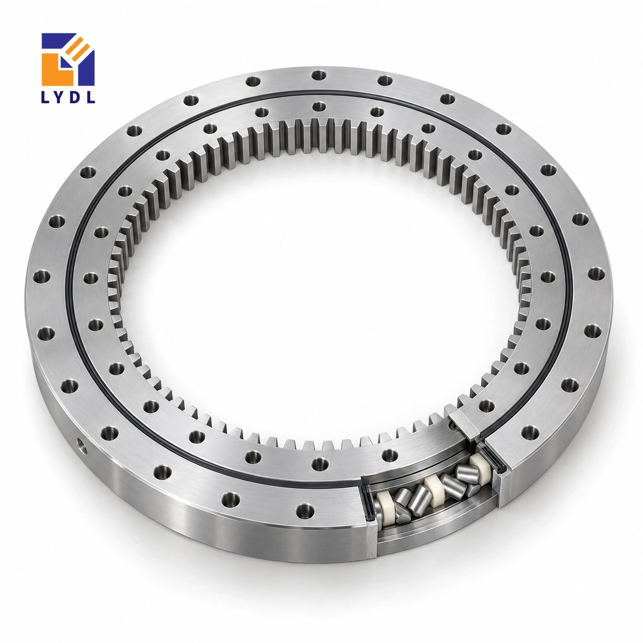
The XI120288 internally geared slewing bearing is a crossed roller reference measuring 216 × 340 × 38 mm. Its internal gear is listed with module 4 and 56 teeth, placing the drive interface inside the ring rather than around the outside perimeter.
XI120288: nominal LYDL listing. Original reference: Catalogue 404. Supplied execution requires an agreed drawing.
XI specification tables · Family technical reference
| Bore (mm) | Outside (mm) | Height H (mm) | Mass ≈ (kg) |
|---|---|---|---|
| 216 | 340 | 38 | 12 |
| Outer PCD La (mm) | Inner PCD Li (mm) | Outer holes na | Inner holes ni | Hole dB (mm) | Secondary h (mm) |
|---|---|---|---|---|---|
| 324 | 252 | 20 | 20 | 9 | 33 |
| Pitch d0 (mm) | Module m (mm) | Teeth z | Width b (mm) |
|---|---|---|---|
| 224 | 4 | 56 | 34 |
The 224 mm gear pitch diameter is a transmission dimension, while 216 mm identifies the nominal bore. A pinion working inside the ring occupies part of the central equipment space. Draw its motor, support bearings and adjustment travel before committing a rotary union or cable column to that opening. Verify the gear geometry and backlash on the accepted drawing; module and tooth count alone do not fully specify the mesh or an allowable driving force.
The reference has twenty fixing positions per ring on 324 mm and 252 mm circles. The series table also lists centring-execution dimensions separately; do not substitute the smaller centring diameter for the basic outside envelope.
Prepare two drawings for an internal drive: the installed section and the service-removal position. The pinion shaft may clear the product-feed tube during operation yet have no axial withdrawal route once its motor is installed. Identify whether the pinion bracket is adjustable independently of the bearing connection. Changing the bracket to set mesh should not unintentionally disturb the locating relationship between the two supporting structures.
Show the measurement access needed for the agreed backlash check. A drive hidden inside the ring still needs a repeatable inspection method. For an antenna arrangement, distinguish commanded motor motion from actual output movement at the dish or measurement target. Bracket compliance, transmission clearance, control response and structural deformation can each contribute to pointing behaviour.
Request acceptance criteria at the location relevant to the equipment rather than assigning the complete pointing error to the ring. The 56-tooth reference is useful for identifying the mesh, but a ratio calculation also requires the mating pinion and any gearbox stages. Keep those transmission details in the enquiry so the mechanical and control layouts use the same assumptions.
The XI120288 gear row describes internal teeth with module 4 and 56 teeth. Their product is 224 mm, matching the listed nominal pitch diameter. That arithmetic checks the relationship between three entries; it does not calculate a permissible tooth force. The physical outside diameter is 340 mm and the bore is 216 mm, so neither should be replaced by the pitch-circle value in a clearance drawing. Overall height H is 38 mm. Locate the gear face and the two mounting planes from the offered section before positioning a pinion. The tooth form, engagement, quality requirement and supplied material execution remain separate specification items. Keeping these definitions distinct prevents a correct transmission number from being used as the wrong housing dimension.
Begin with the part being inspected and the direction from which the measuring head approaches it. A rotating fixture can expose several faces without repeatedly lifting the workpiece, but its usefulness depends on access around the chuck, brackets and transmission. Sketch the inspection volume above the 216 mm bore and locate any stationary central equipment. Then add the internal pinion assembly rather than treating the opening as entirely available.
Describe the required positions and whether observations are made while moving or after a dwell. Include the workholding mass and any force introduced by probes or auxiliary clamps. If the fixture must return to a datum from both directions, state that requirement at the measurement location. The component reference alone does not define the accuracy of the table, encoder, fixture and drive acting together.
An internal mesh brings the transmission into the centre of the machine. Show the pinion shaft bearings, bracket fasteners and the path by which their reactions reach the base. A drawing that shows only the motor body can omit the structure that controls relative movement at the mesh. Include adjustment and removal space around the bracket, together with access for observing engagement.
The listed 56 teeth provide one part of a ratio calculation; the proposed pinion supplies the other part. Specify its actual geometry and ask for confirmation of a suitable pairing. Define where backlash is evaluated and the operating condition used for that observation. Do not convert a nominal module into a promise about the output position, noise or torque. Those results depend on the agreed tooth execution and the complete drive arrangement.
The independently matched original reference includes an N suffix. Retain that distinction when exchanging drawings: the LYDL designation on this page identifies the enquiry, while the offered configuration must be resolved in its own documentation. Compare the complete section, attachment features and application requirements before recording any replacement decision. Similar dimensions alone do not approve interchange.
For a first article, identify which dimensions are receiving checks and which observations belong to the finished inspection station. Record the support condition when measuring the ring. On the assembled fixture, use a repeatable target, approach direction and workholding state. This separates a component observation from fixture seating, transmission behaviour or measuring-system error without assigning an unsupported precision grade to the bearing.
Attach the fixture section, intended duty and required measurement result to the model enquiry. Show the 324 mm outer and 252 mm inner connection circles on the mating parts, including the actual screw and pilot details once agreed. Explain how the fixture will be cleaned and what particles or fluids can reach the central mesh.
For shipment, describe whether the component is delivered loose or within a larger assembly and identify the surfaces that need protection. Keep the received identification associated with its drawing revision. If a test result is requested, specify the characteristic and observation method before ordering. A generic workshop photograph or packing illustration cannot supply that evidence for an individual inspection machine.
XI120420 changes the internal gear from 56 to 85 teeth while keeping module 4. Its nominal envelope grows to 332 × 486 × 39 mm from 216 × 340 × 38 mm here. A retained pinion would therefore see a different tooth-count relationship, and the nearly unchanged height does not preserve the radial installation.
For the inspection fixture, put the optical or probe access on both sketches and locate the pinion bracket. The smaller reference may be easier to package, while the larger bore may serve a specific central requirement. Neither observation approves a load or an accuracy result. Compare the full offered sections and operating cases before selecting, and preserve the N-suffix distinction associated with the independently matched original reference.
A compact antenna positioning assembly is an illustrative layout. Study wind moments and cable twist independently of the pinion drive, and define the pointing requirement for the complete system.

Request a gear inspection scope appropriate to the agreed mesh and a stated running-test condition. Packaging should keep contact loads away from the internal teeth and mounting datums.

XI120288 carries internal teeth; XA120235 is externally geared. The drive location and complete mounting envelopes differ, so they require separate layouts.
The reference gives 56 teeth at module 4 and a 224 mm pitch diameter. Gear quality and mesh acceptance need separate specification.
No. The bore reference is 216 mm, while the pitch diameter is 224 mm. The internal pinion still occupies part of the opening.
The cited original reference is XI120288-N. LYDL supply requirements must be agreed separately rather than inferred from that reference designation.
Geometry is only part of that review. Supply torque, duty, gear requirements and support details to establish the applicable limits.
External gearing: XA series. Standard internal-gear group: XSI range.
Send the pinion specification, available central space and required backlash for XI120288 review.