

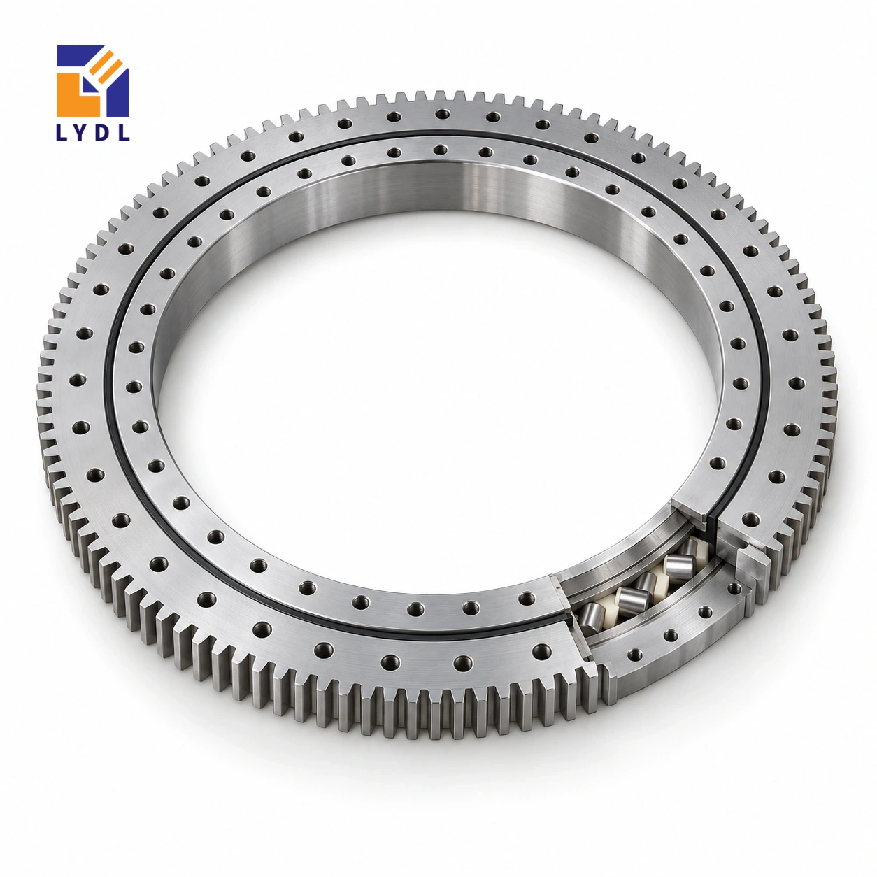
XA260560 is listed as an external gear cross roller reference with a 456 mm bore, 708 mm outside diameter and 68 mm height. Its module 10 gear has 69 teeth, making it a distinct drive-interface choice within the requested XA group.
XA260560: nominal LYDL listing. INA interchange unverified. Supplied execution requires an agreed drawing.
XA specification tables · Family technical reference
| Bore (mm) | Outside (mm) | Height H (mm) | Mass ≈ (kg) |
|---|---|---|---|
| 456 | 708 | 68 | 90 |
| Outer PCD La (mm) | Inner PCD Li (mm) | Outer holes na | Hole dB (mm) | Secondary h (mm) |
|---|---|---|---|---|
| 624 | 496 | 28 | 18 | 61 |
| Pitch d0 (mm) | Module m (mm) | Teeth z | Width b (mm) |
|---|---|---|---|
| 690 | 10 | 69 | 61 |
Do not compare this model with a nearby module 5 or module 6 ring using outside diameter alone. The listed pitch diameter is 690 mm and the gear width is 61 mm, but pinion tooth form, engagement, backlash and support remain necessary design inputs. Describe output torque across the duty cycle, including reversals and stopped loads. A coarser listed module is not a standalone statement that a bearing or gear can carry a larger application load.
The source gives twenty-eight outer fixing positions on a 624 mm circle, 18 mm holes and a 496 mm inner circle. Check the pinion bracket against the bolt-access and guard-removal envelopes.
Provide a pinion definition that includes tooth geometry, supported shaft dimensions, axial engagement and the intended material or treatment requirements where applicable. These are specification requests, not properties implied by the ring listing. Show the support bearings and the pinion overhang on the bracket section. Include the way the bracket is adjusted and secured, because that arrangement influences alignment under load.
For the platform, list each major moving component with its distance from the axis instead of supplying only a total mass. State acceleration and braking conditions and identify any payload position that changes during movement. An emergency stop can differ from the normal programmed stop, so describe it separately. Check whether the twenty-eight-position outer connection can be tightened with the drive installed or whether the assembly sequence must place the pinion afterwards.
The inner interface and locating details need the complete offered drawing before machining. Plan guard removal and access to confirmed service points within the actual machine footprint. A coarse module may be a useful design choice, but it does not replace gear-strength, connection or bearing-load assessment. Keep those decisions tied to the supplied execution and duty rather than interpreting size as a performance rating.
The final enquiry should make the intended complete transmission identifiable.
The XA260560 gear row describes external teeth with module 10 and 69 teeth. Their product is 690 mm, matching the listed nominal pitch diameter. That arithmetic checks the relationship between three entries; it does not calculate a permissible tooth force. The physical outside diameter is 708 mm and the bore is 456 mm, so neither should be replaced by the pitch-circle value in a clearance drawing. Overall height H is 68 mm. Locate the gear face and the two mounting planes from the offered section before positioning a pinion. The tooth form, engagement, quality requirement and supplied material execution remain separate specification items. Keeping these definitions distinct prevents a correct transmission number from being used as the wrong housing dimension.
The gear row combines module 10 with 69 teeth and a 690 mm pitch circle. This differs substantially from a neighbouring module 6 arrangement even when outside sizes appear similar. Identify the actual pinion instead of retaining one on the strength of a close bearing envelope. Review tooth geometry, axial overlap and the bracket section as one proposed drive.
The listed bore is 456 mm and the outside diameter is 708 mm. Put the central equipment and peripheral transmission on the same layout. Include the path for removing the motor and pinion after the platform is assembled. Space reserved only for normal rotation can overlook the tools and travel needed for transmission maintenance.
A production station may use the same base with several fixtures. Provide a schedule of those fixtures with their moving mass, centre of gravity and relevant process forces. Include empty and partially occupied states if they occur during handling. A large tool located close to the axis can differ from a lighter one with a long overhang.
Describe acceleration and stopping for each meaningful configuration. If a mechanical restraint is used during processing, show its connection and when it engages. The application assessment needs these force paths to distinguish the ring's task from the transmission and restraint. The approximate 90 kg component mass should be used for component handling, not as a proxy for any permitted workpiece weight.
Overall H is 68 mm, with h and the listed gear width both 61 mm. Use a labelled section to place the two seating planes and the tooth face. Confirm that the chosen pinion height and supporting adapter refer to the correct surfaces. Equal numbers in the row do not replace a section drawing.
Twenty-eight fixing positions are listed at each ring, on circles of 624 mm and 496 mm. Check screw form, engagement and access against the offered execution. Review the actual backing, especially near a motor bracket, pocket or large central cutout. The base should present an agreed seating condition before assembly rather than depend on the ring to correct fabrication distortion.
Provide LYDL with the intended mating geometry, operating cases and required output observation. Original-brand correspondence has not been independently established for this extended XA reference, so any replacement proposal needs its own complete drawing comparison. Identify constrained features and resolve differences before release.
Discuss the environment reaching the external teeth, including particles and cleaning, and preserve access to confirmed service points. Specify the evidence required at delivery separately from the machine test. Store the accepted bearing and pinion information together. A later tooling or transmission change can then be reviewed against the actual purchased configuration rather than against a model number alone.
XA240574 has a nearby 480 mm opening, but its 695 mm outside diameter is smaller than the 708 mm listed here and its 77 mm total height is larger than this 68 mm row. It uses module 5 with 137 teeth rather than module 10 with 69 teeth. Similar physical scale conceals a very different pinion interface.
Compare the proposed tooling, support and drive on complete sections. The eighteen-position attachment of XA240574 also needs a different mating review from the twenty-eight positions here. Identify whether opening, working plane or transmission is the machine's fixed constraint. Then obtain the individual offered execution for that choice and assess the actual duty rather than deriving compatibility from neighbouring designations.
A material-handling platform with a perimeter drive is a representative scenario. Include emergency deceleration and load eccentricity at the maximum working radius.

Agree an inspection scope for the specified mesh rather than accepting a photograph as tooth verification. Protect the outside gear from handling impacts and identify matching accessories separately.

Module 10 is listed, together with 69 teeth and a 690 mm pitch diameter. Confirm the remaining tooth specification with LYDL.
The current row gives 456 × 708 × 68 mm and approximate mass 90 kg.
No. Gear loading and raceway loading require their own checks under the actual supplied execution and duty.
Twenty-eight positions are listed on a 624 mm circle, with 18 mm holes. The inner fixing circle is 496 mm.
This is an extended LYDL row, not an independently verified original-brand interchange specification. An accepted drawing defines the ordered configuration.
Pinion inside: XI series. Standard external-gear group: XSA range.
Send module 10 pinion details and the full torque-time profile with the XA260560 enquiry.