

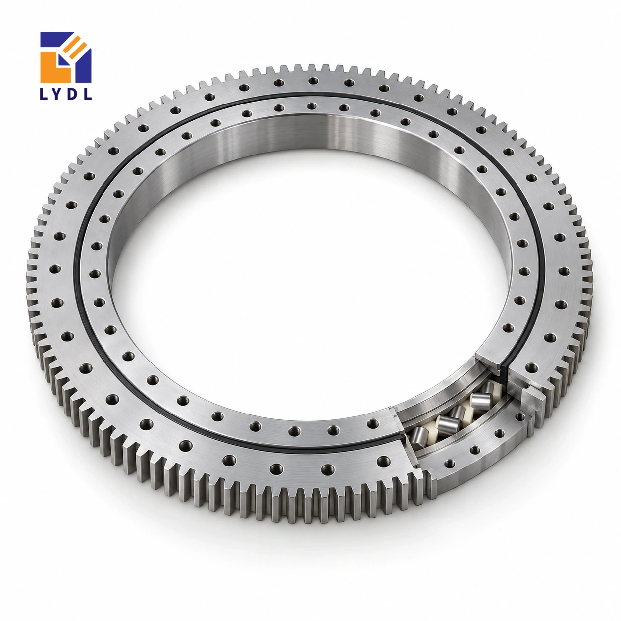
XA260475 is an externally geared cross roller reference in the LYDL range, with a 382 × 598.2 × 65 mm envelope. The listed transmission uses module 6, 98 teeth and a 588 mm pitch diameter.
XA260475: nominal LYDL listing. INA interchange unverified. Supplied execution requires an agreed drawing.
XA specification tables · Family technical reference
| Bore (mm) | Outside (mm) | Height H (mm) | Mass ≈ (kg) |
|---|---|---|---|
| 382 | 598.2 | 65 | 64 |
| Outer PCD La (mm) | Inner PCD Li (mm) | Outer holes na | Hole dB (mm) | Secondary h (mm) |
|---|---|---|---|---|
| 540 | 410 | 36 | 16 | 60 |
| Pitch d0 (mm) | Module m (mm) | Teeth z | Width b (mm) |
|---|---|---|---|
| 588 | 6 | 98 | 60 |
The table gives a 60 mm gear width within the 65 mm overall bearing height. Place the pinion engagement and its bracket reactions on the same section as the supporting flange. A tall engagement zone still needs appropriate alignment and mounting stiffness; it does not independently define a torque rating. Include starts, stops and any impact from reversing the load, then confirm the applicable gear and bearing limits for the offered execution.
Thirty-six outer fixing positions are listed on a 540 mm circle, with 16 mm holes and a 410 mm inner fixing circle. The full locating and inner-hole details need the LYDL drawing.
Describe a reversing sequence with its start position, target angle, acceleration, dwell and return movement. State whether the load is balanced about the axis or whether gravity assists one direction and opposes the other. Those conditions change the force history at the transmission and should not be condensed into one average torque. Provide the motor, gearbox and pinion data in the same request so their relationship is clear.
The bracket that supports the pinion must return its reactions into the fixed structure. Show its attachment, section and adjustment mechanism, including any local opening in the base. Verify the engagement zone relative to the reference gear face in a section through the loaded arrangement. A generous listed width does not remove alignment requirements.
For an elevated welding fixture, draw the centre of gravity and clamp forces at the positions that bound the operating range. Distinguish the weight-driven moment from forces applied by tooling or an operator. Record which events can occur during motion and which occur only after the platform stops. Establish the equipment acceptance point, such as a location on the fixture, and the condition in which displacement is measured.
This supports a practical rigidity requirement without assigning all system movement to the bearing. During installation planning, check how the large external guard is removed and where the pinion shaft can be withdrawn. Ensure these operations do not require loosening a ring that otherwise remains serviceable. Finally, agree the supplied drawing, gear specification and inspection scope together.
The LYDL website row is the starting reference; it does not state the original-brand identity or an allowable reversing torque for the final machine.
The XA260475 gear row describes external teeth with module 6 and 98 teeth. Their product is 588 mm, matching the listed nominal pitch diameter. That arithmetic checks the relationship between three entries; it does not calculate a permissible tooth force. The physical outside diameter is 598.2 mm and the bore is 382 mm, so neither should be replaced by the pitch-circle value in a clearance drawing. Overall height H is 65 mm. Locate the gear face and the two mounting planes from the offered section before positioning a pinion. The tooth form, engagement, quality requirement and supplied material execution remain separate specification items. Keeping these definitions distinct prevents a correct transmission number from being used as the wrong housing dimension.
The listed 382 mm bore and 598.2 mm outside diameter define the bearing envelope, while the external drive extends the equipment footprint. Draw the pinion assembly on the same plan as the fixture and neighbouring process equipment. Include guard opening and motor-removal space. An arrangement that rotates freely can still be difficult to maintain in a crowded production cell.
For the vertical layout, use the 65 mm total height with the actual flange stack. Place the workpiece's important force locations relative to that seating. The 64 kg approximate component mass helps plan receipt and handling; it is not a capacity statement for the completed positioner. Ask for handling provisions applicable to the offered component.
The nominal row lists 98 teeth, a 588 mm pitch circle and a 60 mm gear width. Show the pinion face relative to the actual tooth section and confirm the proposed engagement. Neither a wider face nor a larger module alone establishes a permissible drive load. The offered material, tooth execution, support and duty are still needed.
List movement time, frequency, normal reversals and relevant stop conditions. If a process tool acts while the table is held, identify the restraint and reaction path. Give the drive supplier the actual pinion arrangement rather than only a desired output torque. This connects the geometry in the product table to the transmission that will be built.
The 540 mm outer and 410 mm inner circles each list thirty-six positions. Place their screw seats, engagement and locating features on the accepted interface drawing. Review whether the supporting flange remains continuous beneath them. A central opening, lightening pocket or bracket attachment may concentrate the structural review in a particular sector.
Specify how the seating is checked after fabrication and how the ring is supported during installation. Confirm a practical tightening and inspection sequence around the circumference with the drive present. The connection must be evaluated with the actual mating material and structure. Fastener quantity alone cannot substitute for that assessment or justify a claimed permissible fixture load.
The LYDL listing identifies the reference geometry, but a complete original-brand cross-reference has not been verified for XA260475. Send the existing interface drawing if interchange is part of the request and mark every feature that must remain compatible. Resolve any proposed difference before machining or purchase.
Define acceptance in terms of agreed component checks and a separate installed observation under the relevant fixture condition. Include the environment, cleaning method and service access in the offer discussion. The application montage and packing reference explain possible uses and general concepts; they are not a record of this model's approval, test results or shipment.
XA260560 changes the opening from 382 to 456 mm and the outside envelope from 598.2 to 708 mm. Its nominal height is 68 mm versus 65 mm here, but the transmission changes more markedly: module 10 and 69 teeth replace module 6 and 98 teeth. The fixing count also changes from thirty-six to twenty-eight positions.
If more central space is required, check the complete revised drive and support rather than simply enlarging a flange. Show the real tooling and force heights on the chosen layout. Neither a wider opening nor a larger module establishes that the proposed process is covered. Request the appropriate supplied execution, pinion assessment and inspection scope for the actual machine.
A welding-positioner table carrying a tall fixture is a representative case. Include gravitational imbalance at every rotation angle and evaluate the bracket support under the external pinion force.

Agree how gear alignment and locating faces will be inspected. A transport cradle should support the ring without resting its weight on exposed tooth tips.

LYDL lists 382 mm bore, 598.2 mm outside diameter and 65 mm overall height, with approximate mass 64 kg.
The row gives 60 mm gear width. That dimension is separate from the 65 mm total bearing height.
Thirty-six outer positions on a 540 mm circle are listed, with 16 mm holes. The inner fixing circle is 410 mm.
It does not. Tooth specification, material execution, engagement, support and duty all affect the applicable transmission limit.
Use the LYDL listing to begin the enquiry, then agree the exact designation, drawing and acceptance requirements for supply.
Pinion inside: XI series. Standard external-gear group: XSA range.
Provide XA260475 with the pinion support section, reversing duty and fixture-centre-of-gravity positions.