

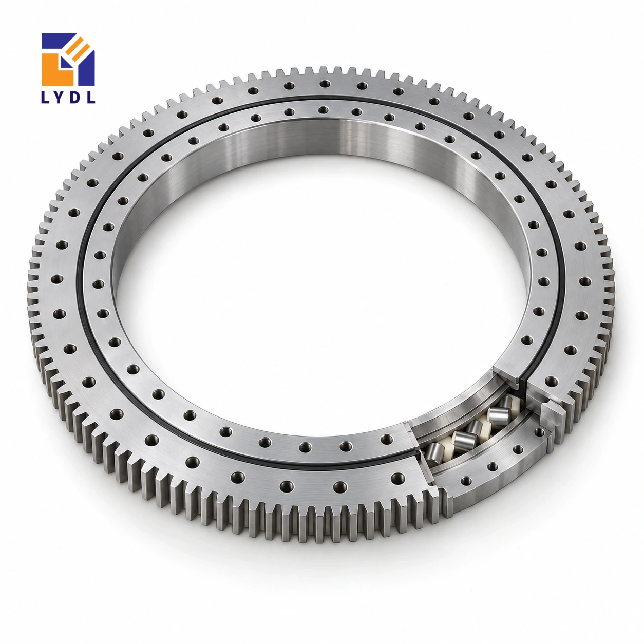
The XA120235 externally geared slewing bearing is a crossed roller reference with a 171 mm bore, 318.8 mm outside diameter and 40 mm height. Its module 4 external gear places the drive at the perimeter and is listed with 78 teeth.
XA120235: nominal LYDL listing. Original reference: Catalogue 404. Supplied execution requires an agreed drawing.
XA specification tables · Family technical reference
| Bore (mm) | Outside (mm) | Height H (mm) | Mass ≈ (kg) |
|---|---|---|---|
| 171 | 318.8 | 40 | 13 |
| Outer PCD La (mm) | Inner PCD Li (mm) | Outer holes na | Hole dB (mm) | Secondary h (mm) |
|---|---|---|---|---|
| 275 | 195 | 12 | 13 | 35 |
| Pitch d0 (mm) | Module m (mm) | Teeth z | Width b (mm) |
|---|---|---|---|
| 312 | 4 | 78 | 35 |
The 312 mm pitch diameter describes gear engagement, not the maximum outside size. Reserve space beyond the 318.8 mm outer envelope for the mating pinion, support and guard. The internal opening remains available for other equipment subject to the inner connection and actual machine layout. Define the pinion specification and backlash requirement before using module and tooth count to finalise a drive; those two values do not state tooth quality or permissible torque.
The LYDL fixing entry gives twelve outer positions on a 275 mm circle and a 195 mm inner circle. Verify the complete inner pattern, screw seats and locating features on the accepted drawing rather than inferring missing details.
Keep the ring outside envelope, gear pitch circle and pinion position as three separate elements on the layout. The pitch circle describes engagement; it is not a physical clearance boundary for a guard or adjacent machine frame. Add the pinion body, shaft support, motor and adjustment travel before checking maximum machine width. If the platform surrounds a fixed feed, identify how that feed is supported independently of the ring.
A wide clear centre does not make every possible bracket arrangement acceptable. Trace the workpiece force into the rotating plate, through the bearing connection and into the base. Then trace the pinion reaction through its bracket. These paths may load the same fabrication differently.
For a small positioner, specify how the workpiece is clamped and whether a process force acts while rotation is stopped. State what movement or deflection the equipment can accept at the actual working point. A generic description of smooth rotation cannot serve as that acceptance requirement. Original XA120235-N geometry is a useful comparison source, but the ordered LYDL execution, mesh requirements and inspection conditions should be written into the supply documentation.
This keeps catalogue identity, machine design and delivery acceptance connected without treating them as the same evidence.
The XA120235 gear row describes external teeth with module 4 and 78 teeth. Their product is 312 mm, matching the listed nominal pitch diameter. That arithmetic checks the relationship between three entries; it does not calculate a permissible tooth force. The physical outside diameter is 318.8 mm and the bore is 171 mm, so neither should be replaced by the pitch-circle value in a clearance drawing. Overall height H is 40 mm. Locate the gear face and the two mounting planes from the offered section before positioning a pinion. The tooth form, engagement, quality requirement and supplied material execution remain separate specification items. Keeping these definitions distinct prevents a correct transmission number from being used as the wrong housing dimension.
An external mesh can leave the central region easier to arrange, provided the pinion and its guard fit beside the platform. Start with a section through the 171 mm bore and the proposed drive. Place the workholding, motor support and any stationary services on that section. Include the envelope of moving tooling rather than stopping at the bearing's 318.8 mm outside dimension.
For a compact machine, maintenance space can be more restrictive than operating clearance. Show how a pinion, motor or encoder is withdrawn and where the removed part can be supported. Check access to the fixture fasteners after the guard is installed. These decisions help establish a workable arrangement before the bearing is chosen from a dimensional shortlist.
This nominal listing combines module 4, 78 teeth and a 312 mm pitch circle. A proposed pinion must be reviewed as its actual mating part, with tooth geometry and support identified. The outer tooth envelope is a clearance boundary; the pitch circle describes transmission geometry. Keep those functions separate in the equipment drawing.
The listed 40 mm total height and 35 mm gear width also serve different purposes. Obtain the offered section to position the pinion axially and identify the mounting planes. A catalogue relationship does not supply tooth quality, backlash or permissible torque. If a particular output result is needed, state the working datum and operating condition so the whole transmission can be assessed.
Manual loading can introduce forces that are absent from a simple payload estimate. Describe how a part is placed, located and clamped, including any overhang or operator-applied force relevant to the machine design. Show the workpiece centre of gravity and the tooling that remains attached during movement. List the permitted part variants.
The fixing circles of 275 mm and 195 mm each have twelve listed positions. Add the agreed screw, seat and locating details, and review the backing under both attachment zones. A narrow machine base or a pocket for the motor can interrupt the support near one sector. The installed fixture's behaviour depends on these structures as well as the ring, so do not infer a load limit from the fastener count.
An original XA120235-N reference can be matched independently, but the suffix and the proposed LYDL execution still require drawing review. Preserve the supplier identity and offered revision in the purchasing record. Do not turn a shared envelope into an unrestricted replacement statement.
For a sample, agree the component features to be checked on receipt and the separate test of the finished fixture. Record the approach direction, workholding state and measurement location used in the installed observation. Include the actual debris and cleaning environment when discussing protection. Requested inspection evidence should identify the ordered component; the generic packaging montage cannot establish that it was tested or shipped for this application.
XA180309 has a 235 mm bore, 408.4 mm outside envelope and 60 mm height, compared with 171 × 318.8 × 40 mm here. Its module 5, eighty-tooth gear differs from the module 4, seventy-eight-tooth mesh of XA120235. It also changes the fixing count from twelve to twenty-four positions.
For a compact hand-loaded fixture, determine whether a larger opening is actually needed and show the new working plane if it is. Retaining a motor or bracket requires a separate pinion and alignment review. The smaller reference has an independently matched original N-suffix counterpart; that evidence does not extend automatically to the larger LYDL row. Resolve the offered identity and complete interfaces for whichever candidate suits the machine.
A small welding positioner is one representative layout. The external pinion can be examined for access, spatter shielding and clearance through the full workpiece rotation.

Agree the gear and flange measurement requirements with the supplied execution. Protect the exposed teeth and keep straps away from tooth tips during delivery.

The reference uses external teeth, module 4, 78 teeth and a 312 mm pitch diameter. Confirm the complete mesh specification separately.
No. The outside diameter is listed as 318.8 mm; 312 mm is the gear pitch diameter.
Catalogue 404 includes XA120235-N. It is a reference for comparison, while LYDL delivery details belong to the agreed drawing and order.
Check the model drawing. This page retains the listed outer count and does not turn an omitted inner detail into a machining instruction.
Review guarding, spatter exposure and maintenance access in the equipment design. Do not assume the pictured gear is protected in the installed position.
Pinion inside: XI series. Standard external-gear group: XSA range.
Send the XA120235 pinion, guarding concept and workpiece load sketch for drawing review.