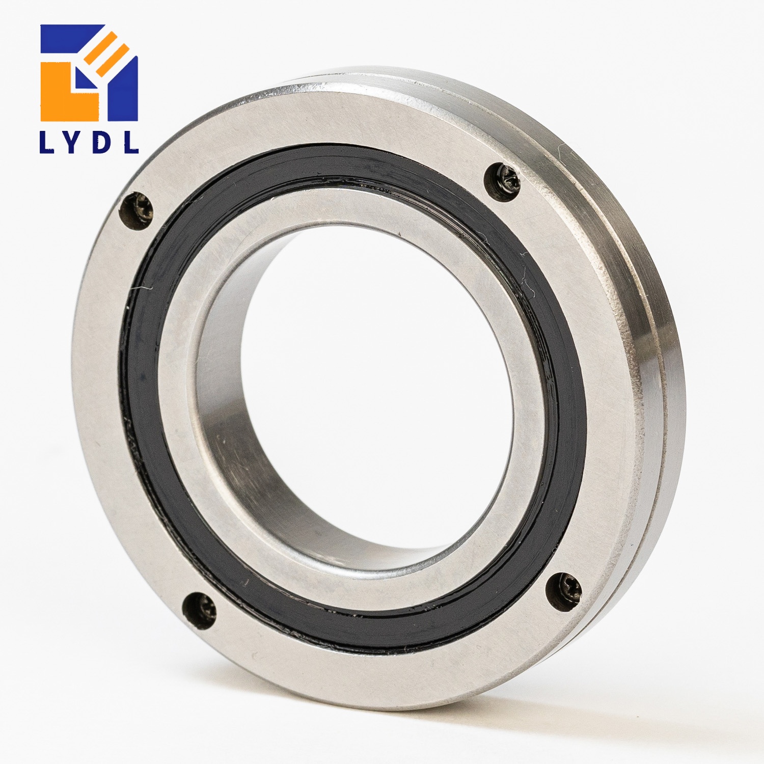
For a torque-motor rotary table, compare YRT and YRTS using the actual motion cycle, combined loads, friction data, thermal conditions and mounting interface. YRTS is a family to evaluate for higher-speed and low-friction direct-drive duties. A torque motor alone does not establish that every axis needs YRTS, and an indexing duty alone does not prove that YRT is suitable.
This guide explains which differences can support a preliminary shortlist and which data are still needed to select the supplied LYDL configuration. It does not assign a universal speed limit or a percentage friction advantage to either series.
What the series distinction tells you
Schaeffler positions YRTS for demanding higher-speed rotary axes and low-friction direct-drive applications. Its technical publication treats speed, friction, lubrication and thermal conditions as parts of the bearing-position assessment. Those are reference-family characteristics, not LYDL test results. Technical reference: TPI 120
| Comparison item | YRT proposal: ask for | YRTS proposal: ask for |
|---|---|---|
| Intended duty | Evidence for the actual indexing, rotation or mixed cycle | Evidence for the actual higher-speed/direct-drive or mixed cycle |
| Speed suitability | Applicable limits and conditions for the exact model | Applicable limits and conditions for the exact model |
| Friction | Starting/running resistance with test conditions | Starting/running resistance under comparable conditions |
| Thermal behaviour | Lubricant, heat input and system heat-transfer assumptions | The same information for the proposed YRTS arrangement |
| Rigidity and accuracy | Defined load directions, mounting scope and inspection method | Equivalent definitions for a meaningful comparison |
| Interface | Complete drawing and fixing arrangement | Complete drawing, not an assumed drop-in interface |
The table is a request for comparable evidence. An empty performance field should remain an identified data requirement rather than be filled with a value from another supplier’s catalogue.
Check whether both proposed models actually exist
LYDL’s YRT/YRTS/YRTM series page lists YRT100 among the YRT examples and YRTS150, YRTS200 and YRTS260 among its YRTS examples.
That does not establish a YRTS counterpart for every YRT size. If a project starts with YRT100, confirm the available YRTS option rather than constructing a part number by adding S. A published typical-model list is also not proof that every unlisted size is unavailable.
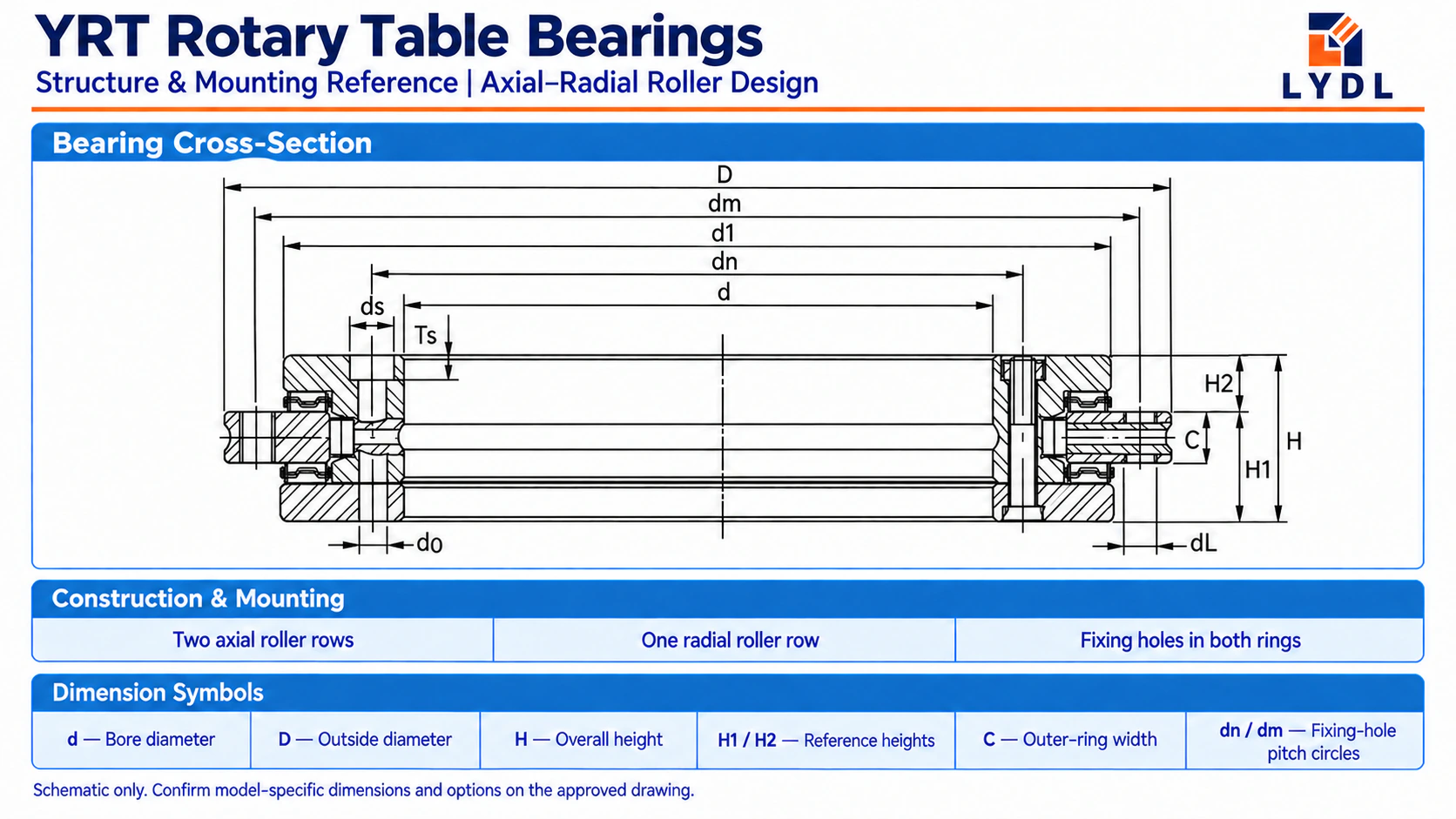
For a replacement, compare the actual bore, outside diameter, height, shoulders, fixing circles, lubrication connections and fastener access. Equal boundary dimensions, where present, do not settle preload, friction, accuracy or installation requirements.
Describe the motion cycle before comparing maximum rpm
Two axes with the same peak speed can impose different bearing and drive requirements. One may index briefly and dwell for most of the cycle; another may rotate continuously under process load.
| Duty stage | Record |
|---|---|
| Acceleration | Starting speed, target speed, duration or profile, loads and equivalent inertia |
| Rotation or process | Speed, duration, force/moment conditions and process torque |
| Deceleration | Speed change, profile and braking conditions |
| Dwell | Duration, holding loads and surrounding temperature |
| Reversal | Angle, rate, repeated cycle and load variation |
For each proposed bearing, ask whether the supplied data cover that cycle. Keep the peak-speed check separate from the sustained thermal assessment.
Short indexing is a reason to examine how much time the axis spends at each condition; it is not an exemption from checking the actual maximum speed.
Compare friction values with matching definitions
Starting torque and running torque answer different questions. Request the relevant values or curves with the speed, direction, temperature, lubricant, load, support condition and test method identified.
Also identify what is included. A measurement of the completed table can include rotary seals, cables, connections, the drive and other mechanisms. It should not be compared directly with a bearing-only value as evidence of a series advantage.
If only a reference catalogue value is available, preserve that limitation in the drive model and define which measurement is required before final acceptance.
Calculate frictional power and time at duty
At steady speed, the mechanical power associated with resisting torque is:
P = 2πnM / 60
P is in watts, n in rpm and M in N·m. These arithmetic examples are assumptions, not YRT/YRTS specifications or LYDL measurements.
| Assumed resisting torque | Assumed speed | Calculated power |
|---|---|---|
| 2 N·m | 60 rpm | 12.6 W |
| 2 N·m | 300 rpm | 62.8 W |
| 5 N·m | 300 rpm | 157.1 W |
Time matters too. Under the simplifying assumption of constant 62.8 W during the powered rotation, 10 seconds corresponds to about 628 J of frictional energy; 600 seconds corresponds to about 37.7 kJ. This calculation uses E = Pt and excludes changes in torque, speed and other heat sources.
The examples explain why an intermittent and a continuous duty need different assessments. They do not predict the bearing temperature. Actual temperature also depends on heat transfer, motor losses, lubrication and the surrounding structure.
Build the motor torque budget separately
A bearing friction number is one contribution to the axis torque requirement. At each motion stage, consider the equivalent rotating inertia and acceleration, external torque about the driven axis, bearing resistance and other applicable losses.
Use a consistent sign convention. Review peak torque separately from continuous thermal capability and apply the drive manufacturer’s method to the actual repeated cycle.
Overturning moment, radial force and axial force must also be evaluated for the bearing and support structure. They are not interchangeable with process torque about the driven rotation axis.
Keep stiffness, runout and positioning as separate requirements
Define the permitted displacement or tilt under load. Compare stiffness information only when its direction, mounting condition and included components match.
Then define mounted runout and angular positioning requirements independently. Good bearing running accuracy alone does not specify encoder performance or the loaded displacement of the complete table.
For thermally sensitive work, identify the warm operating condition under which the table must meet its requirement. A cold inspection and a warmed machining cycle may address different acceptance conditions.
Use a conditional shortlist
| Project condition | Selection action |
|---|---|
| Existing YRT arrangement meets the demonstrated cycle and performance requirements | Keep it in the comparison; identify the reason for changing series |
| Sustained rotation, higher speed or frictional heating is a concern | Evaluate a suitable YRTS proposal using model-specific operating data |
| Bearing friction consumes too much of the drive margin | Compare conditioned measurements or applicable curves for both proposals |
| Required YRTS size or interface is unconfirmed | Obtain the actual proposal drawing before freezing the machine layout |
| Both proposals remain feasible | Compare the complete thermal, displacement, accuracy, drive and commercial requirements |
This route avoids choosing solely from the drive type or a single maximum-speed value.
Prepare a useful comparison request
Send a section drawing and one duty table for both proposals. Include:
- Model references and fixed installation interfaces.
- Central opening, available envelope and fixing access.
- Radial/axial forces, overturning moments and their application points.
- Process torque about the driven axis and motion profile.
- Required runout, loaded displacement and positioning performance.
- Lubrication, environment, thermal conditions and inspection scope.
Ask which performance data are available, what those data include and which conditions must be agreed or measured for the proposed supply.
Common questions
Does a torque motor always require YRTS?
The bearing must meet the axis duty and performance requirements. The motor type is relevant, but does not complete the selection.
Is the difference simply full-complement rollers versus a cage?
Do not apply that blanket explanation across series, sizes and suppliers. Confirm the exact internal construction in the matching product documentation.
Is YRTS automatically interchangeable with YRT?
Check the complete interface and performance specification for the two supplied models. A family name does not establish interchangeability.
Discuss the complete axis with LYDL
Review the LYDL rotary table bearing range and published YRT/YRTS model references, then send LYDL your duty table and section drawing.
A useful comparison connects the bearing proposal to the actual cycle, the required evidence and a defined acceptance method. That is the basis for evaluating YRT and YRTS as parts of a torque-motor table.