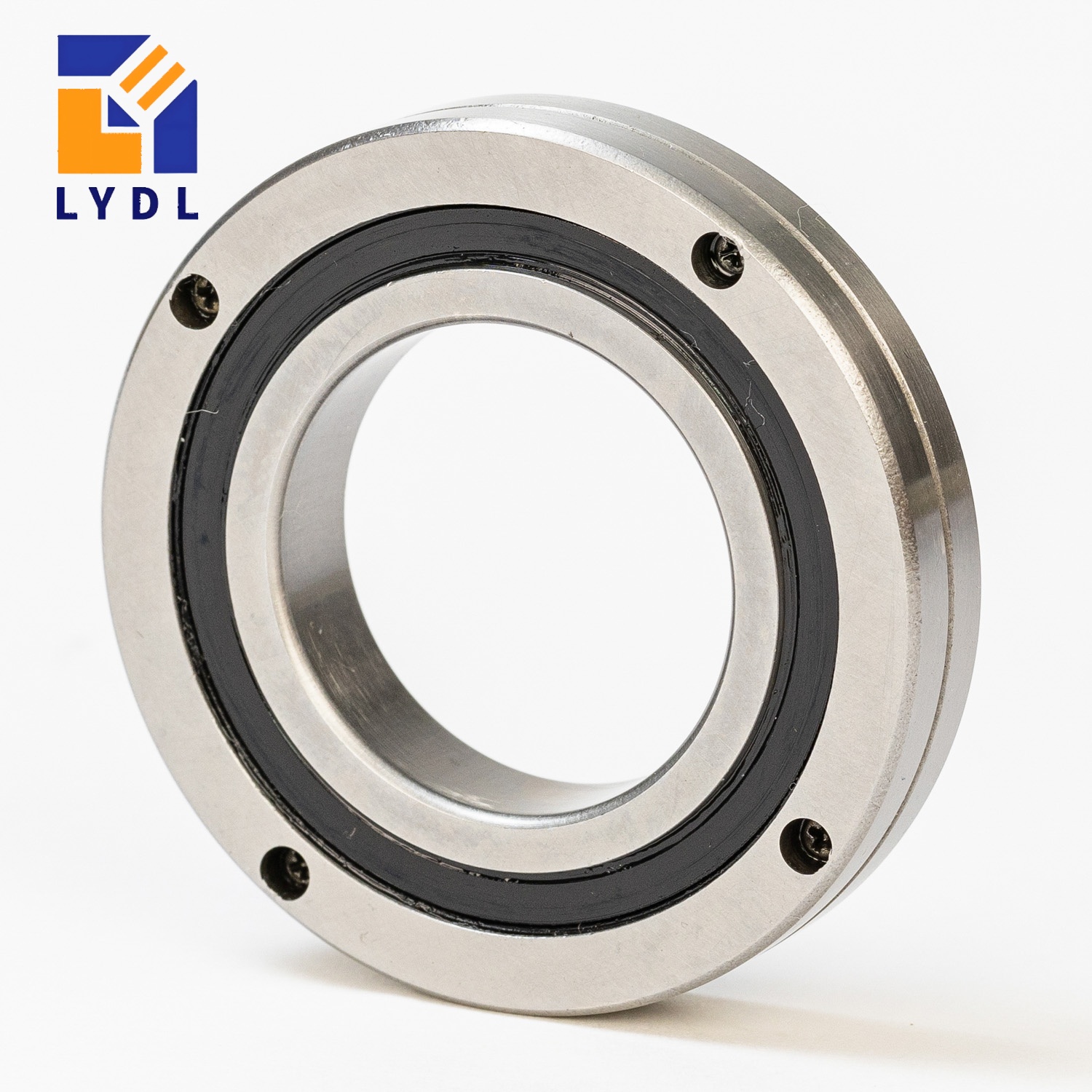
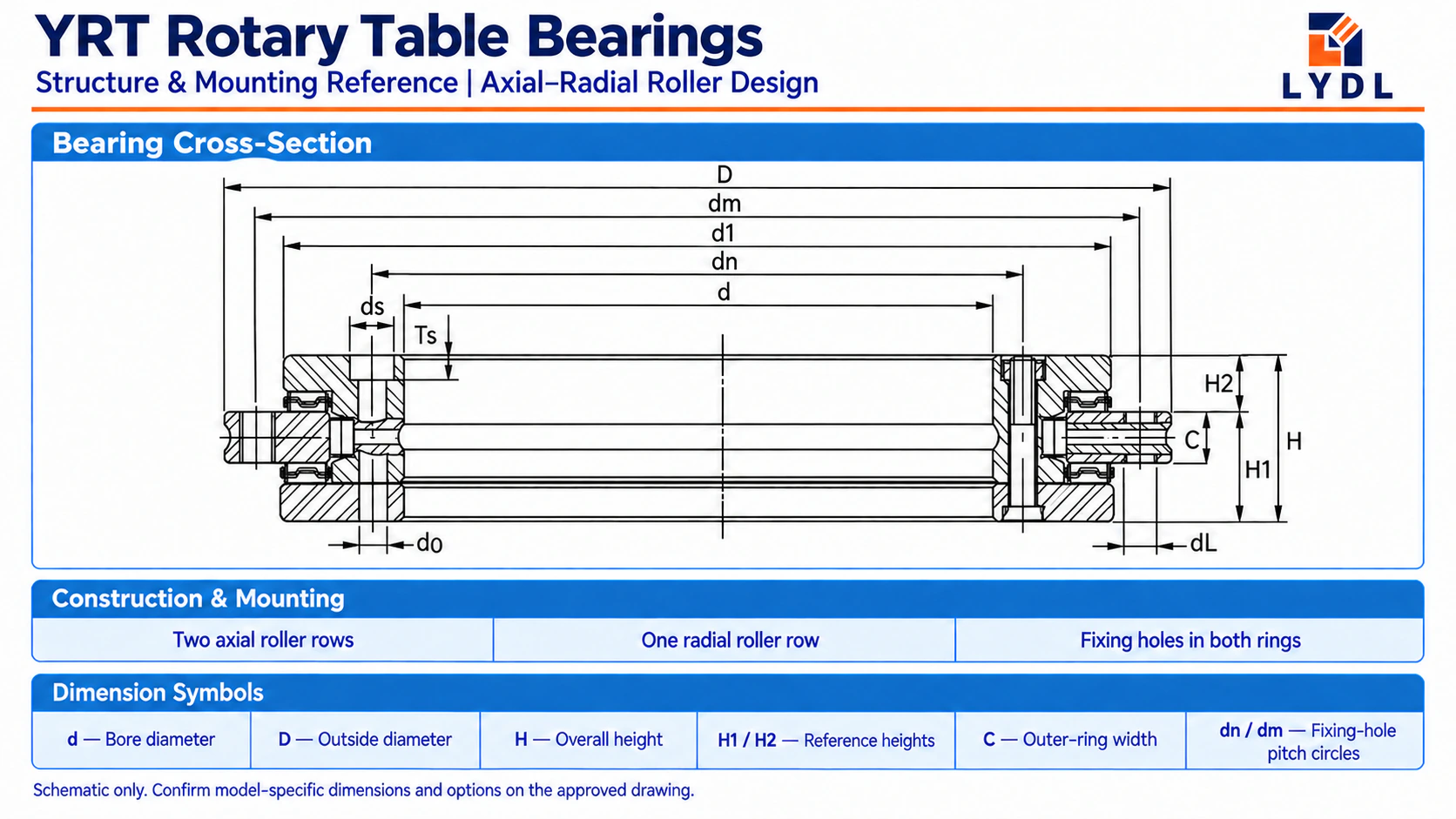
Select a robot wrist bearing by checking the usable central passage, complete mounting envelope, combined loads, loaded displacement and drive duty. RU85 and RU124 are two LYDL crossed roller bearing examples for a hollow, directly mounted arrangement. A larger catalogue model is not automatically the better wrist design.
This guide provides a preliminary screening method. It compares published dimensions and shows how to describe a load case; it does not assign an allowable robot payload or approve a complete joint.
Start with the wrist, then compare the model numbers
The LYDL RU85 information and RU124 product information identify the following envelopes.
| Model | Bearing bore | Outside diameter | Width |
|---|---|---|---|
| RU85 | 55 mm | 120 mm | 15 mm |
| RU124 | 80 mm | 165 mm | 22 mm |
The model numbers are not bore diameters. RU85 provides a published 55 mm bore, while RU124 provides 80 mm.
Those values give three independent packaging checks. A design may need the larger bore but lack the outside-diameter space for the larger bearing. Alternatively, both bearings may fit, leaving load, displacement and drive requirements to decide the shortlist.
The mounting holes, shoulders, tolerances and actual suffixes require the complete drawing.
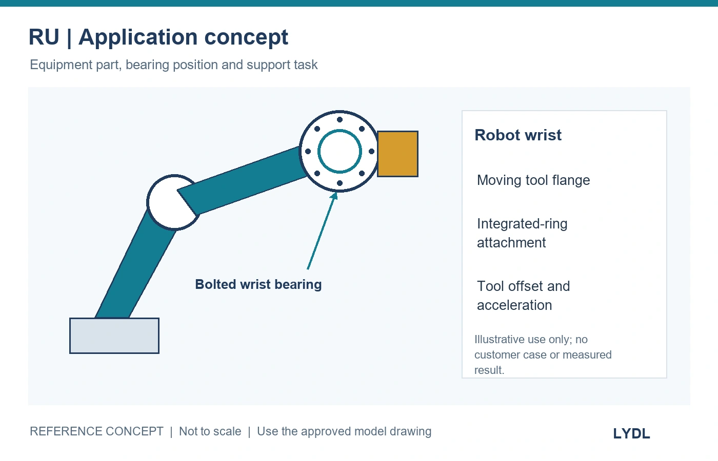
Gate 1: define the passage that the assembled wrist actually needs
The bearing bore is not necessarily the free opening in the completed wrist. A hollow shaft, output flange, connector or rotary connection can reduce the route through the centre.
Record the bearing bore separately from the minimum assembled passage. For moving cables and hoses, include bend radius, connector size and the full motion range.
Consider two illustrative packaging requirements:
| Assumed requirement | What the published envelopes establish |
|---|---|
| A 60 mm unobstructed route through the bearing’s central opening | RU85’s 55 mm bore excludes this route; RU124’s 80 mm bore permits further layout review |
| A maximum bearing outside diameter of 150 mm | RU124’s 165 mm envelope exceeds the restriction; RU85 passes this one dimensional check |
These are hypothetical geometry checks, not completed selections. If both restrictions apply to the same design, neither candidate meets them together. Review another bearing or change the package instead of forcing a choice between these two.
An 80 mm bore also does not guarantee a 60 mm free route after neighbouring parts have been designed.
Gate 2: turn payload into forces and moments
A payload in kilograms is not a bearing load case. The tool and workpiece create forces whose directions and application points change through the robot’s motion.
For a force with perpendicular moment arm e, the moment magnitude is:
M = F × e
The following is a static arithmetic illustration, not an RU85/RU124 rating or LYDL test.
| Assumed force | Perpendicular arm | Calculated moment |
|---|---|---|
| 100 N | 0.08 m | 8 N·m |
| 100 N | 0.16 m | 16 N·m |
Doubling the perpendicular arm doubles this moment. For the real wrist, build a vector load case that includes the tool, workpiece, wrist components, accelerations, process forces and specified exceptional events.
Keep overturning moment separate from torsional load about the rotation axis. Identify both in the coordinate system, together with radial and axial reactions. Their effects enter different parts of the mechanical and drive assessment.
Gate 3: check displacement at the tool
The design may satisfy a load-capacity check and still allow too much tool movement.
Start with the permitted displacement or tilt at the functional point. Then allocate a realistic allowance to the bearing position, supporting plates, reducer, shaft and other relevant components.
For illustration, if the only movement were a small tilt θ, displacement at distance L would be approximately δ = Lθ, with θ in radians. An assumed 0.0001 rad tilt at 0.20 m gives 0.00002 m, or 20 µm. This is geometry, not a prediction for either bearing; the actual wrist can also translate and deform elsewhere.
Ask for stiffness data with the load direction, preload, mounting condition and included structure defined. THK’s moment-rigidity guidance notes the influence of adjacent parts and fixing bolts on bearing-position rigidity. Technical reference: moment rigidity
A larger envelope alone cannot tell you the resulting tool displacement.
Gate 4: check the drive after updating the layout
Changing the bearing can change the output flange, supports, fasteners and routed services. Update the moving mass and inertia model for the proposed complete wrist.
Review:
- Normal and maximum speed.
- Oscillation angle and reversal frequency.
- Acceleration, deceleration and settling requirements.
- Starting and running resistance under defined conditions.
- External process torque about the driven axis.
- Peak and continuous drive capability across the duty cycle.
Do not treat every increase in bearing mass as an equal increase in rotating inertia. Establish which parts rotate and how their mass is distributed relative to the axis.
Gate 5: confirm the mounting and acceptance requirements
RU bearings attach through their ring interfaces. Identify the rotating ring, fixing-hole arrangement, screw approach and support faces before releasing the surrounding parts for manufacture.
For an RU124 proposal, confirm the applicable standard/G/X mounting arrangement against the drawing. A suitable envelope can still be unusable if the screw-access direction conflicts with a neighbouring component.
Specify mounted runout, starting/running resistance and loaded displacement separately. Avoid asking the accuracy grade to stand in for all three.
Use one screening sheet for both candidates
| Review item | Information to record for each proposal |
|---|---|
| Passage | Required free route, connectors, moving-service clearance and narrowest assembled section |
| Package | Bore, outside diameter, width, adjacent parts and tool access |
| Loads | Coordinates, forces, overturning moments and torsional loads for each duty stage |
| Performance | Permitted tool displacement, tilt, mounted runout and rotational resistance |
| Motion | Speed-time profile, accelerations, reversals and operating duration |
| Interface | Rotating ring, hole arrangement, support geometry, seals and lubrication |
| Verification | Drawing revisions, applicable load/life assessment and acceptance method |
Advance a candidate only after it passes the relevant gates. If information is missing, identify that gap instead of interpreting the model number as evidence that the design will work.
Questions about the RU85/RU124 comparison
When should RU124 enter the shortlist?
When the layout needs an opening or support arrangement that justifies its larger envelope and can accommodate it. The full load, displacement and drive checks still apply.
Can an RU85 payload limit be calculated from its bore or catalogue load rating alone?
No. A payload requires its position, motion, load combination, support conditions and the applicable bearing assessment.
What if neither candidate fits the passage and outside-diameter constraints?
Review another architecture or size, or change the package. A two-model comparison should not force an unsuitable selection.
Ask LYDL to review a defined wrist requirement
Start with the LYDL RU series and the RU85 and RU124 entries. Send the wrist section and completed screening requirements, including the interfaces that may change.
Contact LYDL about the robot wrist bearing with the required passage, force application points and permitted tool movement. These inputs turn a model comparison into an application-specific technical discussion.