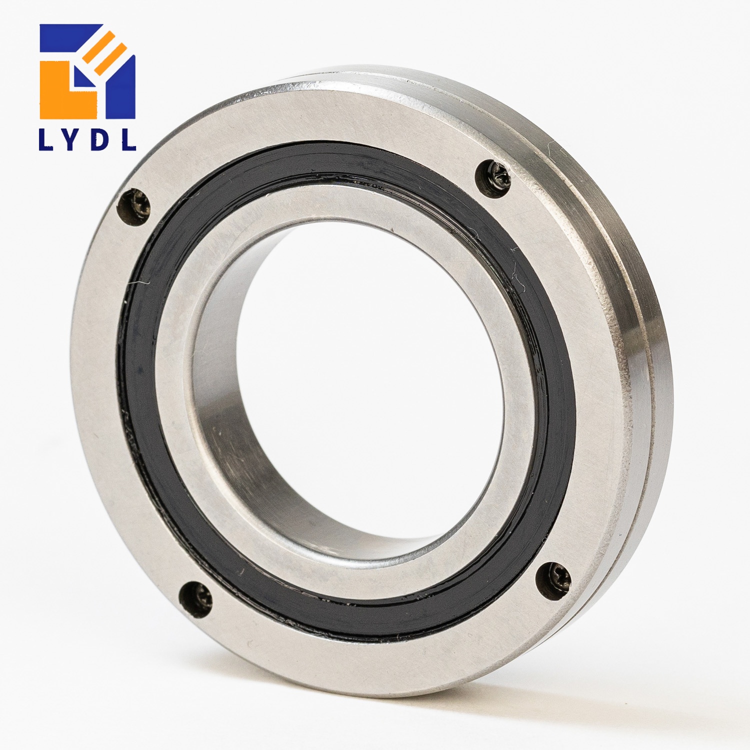
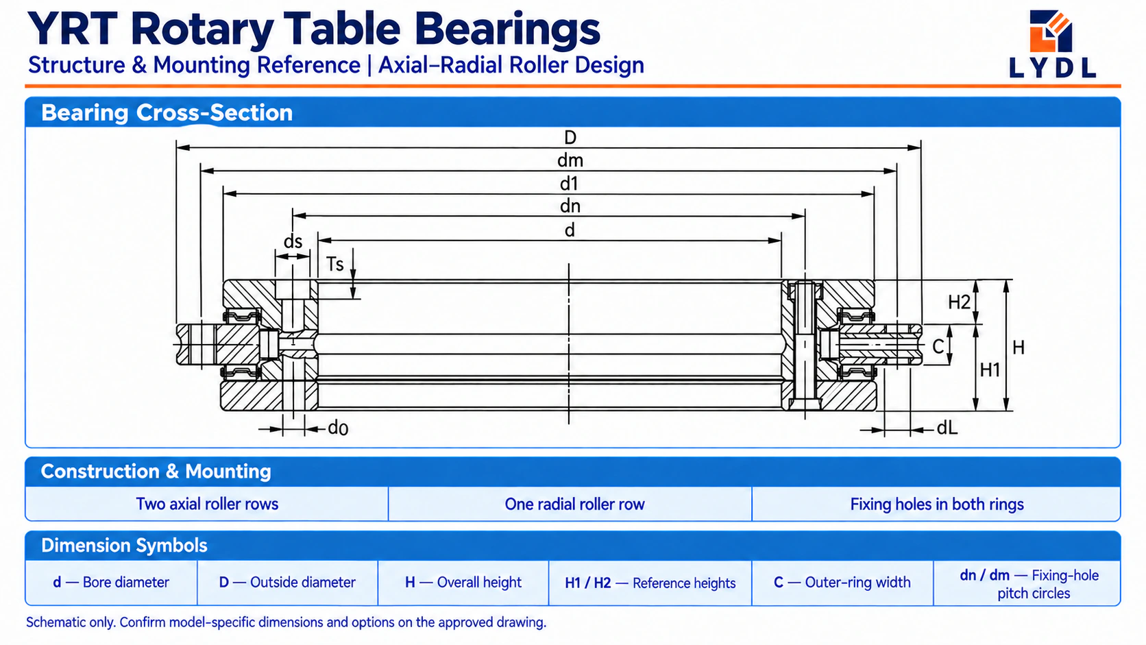
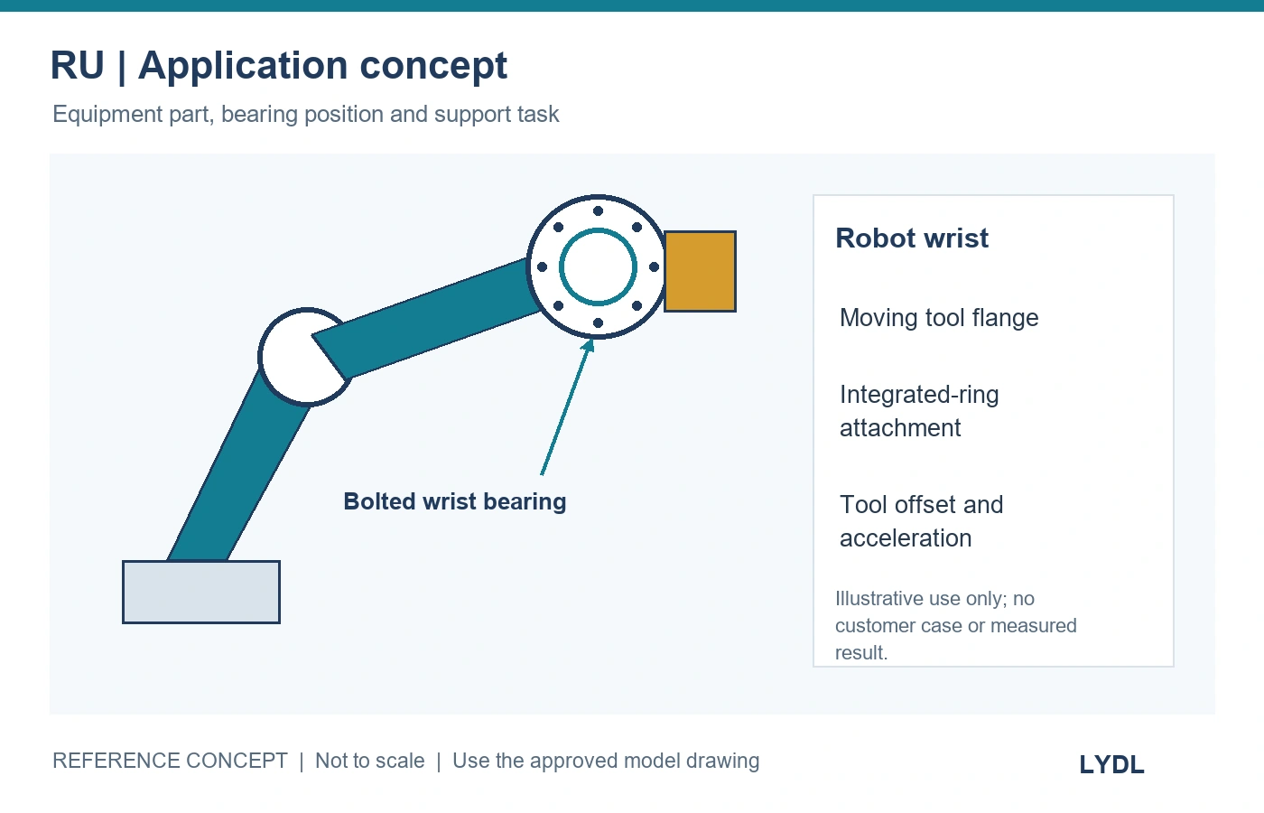
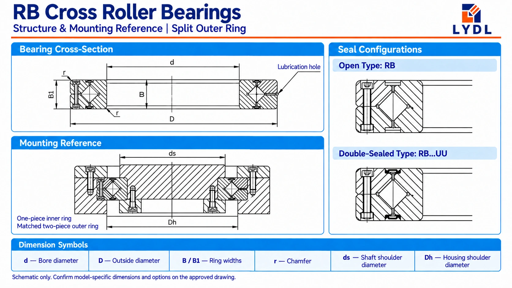
Choose between RB and RU crossed roller bearings by comparing the complete bearing position. RB reference designs use a split outer ring and an integral inner ring, typically for inner-ring rotation. RU uses integral rings with fixing holes for direct attachment. Those differences affect retention, support, bolt access and assembly; they do not establish a universal winner on load capacity, friction or cost.
For a new axis, review the bearing and surrounding parts together. For a replacement, begin with the interfaces that cannot change. The following sequence turns that review into a practical shortlist.
The structural difference that changes the assembly
THK’s model descriptions identify the RB split-outer-ring construction and the RU integrated-ring arrangement. Use these as reference architectures, then check the supplied LYDL drawing. RB construction, RU construction
| Question | RB arrangement | RU arrangement |
|---|---|---|
| Reference ring structure | Split outer ring; integral inner ring | Integral inner and outer rings |
| Main fixing question | How will the seats and retaining components secure the rings? | How will the fixing holes connect each ring to the machine? |
| Adjacent components to include | Shaft/housing seats, shoulders, retaining flanges and their fasteners | Supporting plates, locating features and direct-fixing fasteners |
| Rotating-ring requirement | Check the inner-ring rotation requirement and supplied accuracy scope | Define inner- or outer-ring rotation and the required accuracy scope |
| Main drawing review | Retention, fit, support contact and clearance | Hole pattern, screw access, location and support contact |
Direct fixing can simplify the surrounding arrangement, but RU still needs suitable supporting and locating surfaces. RB’s retaining arrangement also needs to be designed rather than assumed from the bearing dimensions.
Gate 1: identify the rotating ring and controlled output feature
Write down which ring rotates, which ring is fixed and which output feature needs controlled runout. An output flange mounted to one ring creates a different accuracy requirement from a housing rotating around the other.
If inner-ring rotation is required, an RB arrangement can enter the shortlist. If outer-ring rotation is required, review an appropriate RU configuration or another suitable architecture rather than automatically transferring the RB reference arrangement.
This is a shortlist decision. Specify the selected model’s accuracy and installed measurement, particularly when the rotating ring is a purchasing requirement.
Gate 2: compare the complete envelope
A shared bore does not establish a compatible installation. For example, the LYDL RB model listing and RU124 page include these different envelopes:
| Published model | Bore | Outside diameter | Bearing width |
|---|---|---|---|
| RB8016 | 80 mm | 120 mm | 16 mm |
| RU124 | 80 mm | 165 mm | 22 mm |
The shared 80 mm bore is a useful demonstration of why bore matching alone is insufficient. These entries are not presented as equal-capacity alternatives.
For each candidate, add the supporting shoulders, retainers or plates, screw heads, working clearance and assembly-tool access to the section drawing. Compare that complete stack with the available radial and axial space.
If a candidate cannot fit the available envelope, resolve the layout before performing a more detailed product comparison. Passing the envelope check still says nothing about whether the candidate meets the load and stiffness requirements.
Gate 3: follow the reaction path through the surrounding parts
Trace each applied force and moment from the output component, through the rotating ring and rolling contacts, into the fixed support and machine structure.
THK’s design guidance emphasises the rigidity of the housing and retaining flange, particularly for separable-ring arrangements. Its shoulder guidance also identifies the importance of intended support contact. Technical reference: housing and flange design
Review the following on both proposals:
- Intended contact at the ring support faces.
- Shoulder and locating dimensions from the matching drawing.
- Thin sections, slots and cut-outs along the reaction path.
- Fixing access and repeatability of the assembly method.
- Clearance to the ring that must rotate freely.
A higher preload is not a substitute for identifying an unsupported or excessively flexible part. Review the permitted loaded displacement at the functional point as well as the bearing’s applicable load information.
Gate 4: decide how location and retention will be achieved
Mark locating surfaces, clamping surfaces and clearance surfaces differently on the assembly drawing. This makes it easier to see whether the design asks one component to perform incompatible tasks.
For RB, identify which parts retain the split outer ring and how the installed arrangement remains evenly supported. For RU, identify which screws enter through each ring or engage a threaded feature, and whether the tools can reach them after neighbouring components are installed.
Do not copy a fit from one series into the other by default. THK provides separate RU and RB/RE fitting guidance, illustrating that the reference architectures need different consideration. Technical reference: fit selection
Gate 5: compare assembly cost with the same scope
Ask both proposals to meet the same loads, duty cycle, mounted runout and resistance requirements. Then compare the parts and operations required to achieve them.
| Cost or production item | RB proposal: record | RU proposal: record |
|---|---|---|
| Bearing | Complete model and configuration | Complete model and configuration |
| Surrounding parts | Seats, retainers and supports | Mounting plates, locating features and supports |
| Controlled features | Machining and inspection requirements | Machining and inspection requirements |
| Assembly | Fixing access, sequence and operations | Fixing access, sequence and operations |
| Acceptance | Supported runout and resistance method | Supported runout and resistance method |
| Service | Removal access and parts affected | Removal access and parts affected |
This is a comparison worksheet, not a prediction that one series always costs less. In an existing machine, the cost of changing surrounding parts can outweigh the bearing-price difference.
A short decision route
| Your project condition | Useful next step |
|---|---|
| Existing shaft/housing seats and retainers must remain | Assess an RB-compatible drawing before redesigning the bearing position |
| New plates can accept direct fixing on both rings | Evaluate an RU layout with complete locating and bolt-access details |
| Outer-ring rotation is accuracy-critical | Check the applicable RU or alternative construction and specify the rotating-ring requirement |
| One candidate fails the envelope | Resolve the package or choose another size/architecture |
| Both layouts fit | Compare combined-load assessment, loaded displacement, resistance and full assembly cost |
Use the route to decide which drawings and data to request. Final selection still requires the actual load case and operating requirements.
Questions that prevent purchasing mistakes
Is RU always a better version of RB?
No. It is a different mounting architecture. The useful comparison concerns the complete axis and its requirements.
Does direct mounting remove the need for a housing?
It can change the form of the surrounding parts. The bearing still needs location, support and a suitable fixing joint, whatever those parts are called.
Can an RB be replaced by an RU with the same bore?
Compare the full interface. The RB8016/RU124 example shows that matching a bore can leave substantial outside-diameter and width differences.
Request two comparable layouts from LYDL
Review the LYDL RB series and RU series with your assembly section. Identify the rotating ring, fixed interfaces, available envelope, load positions, operating cycle and required mounted accuracy and resistance.
Send LYDL the mounting comparison and identify which surrounding parts may change. That gives the bearing enquiry a defined design boundary and makes the two commercial scopes easier to compare.