To inspect runout on a YRT bearing, identify the measured surface, reference, supported mounting state, probe position and acceptance limit before taking a reading. Inspect the specified feature through the agreed rotation and record its maximum and minimum indications. A measurement on the finished table describes that assembly; it does not isolate the bearing contribution.
This guide uses YRT100 as a product example and provides a measurement plan for technical purchasing and assembly inspection. The inspection principles also help structure a discussion about other YRT sizes, while their drawings and limits must be checked individually.
What YRT100 identifies, and what it does not
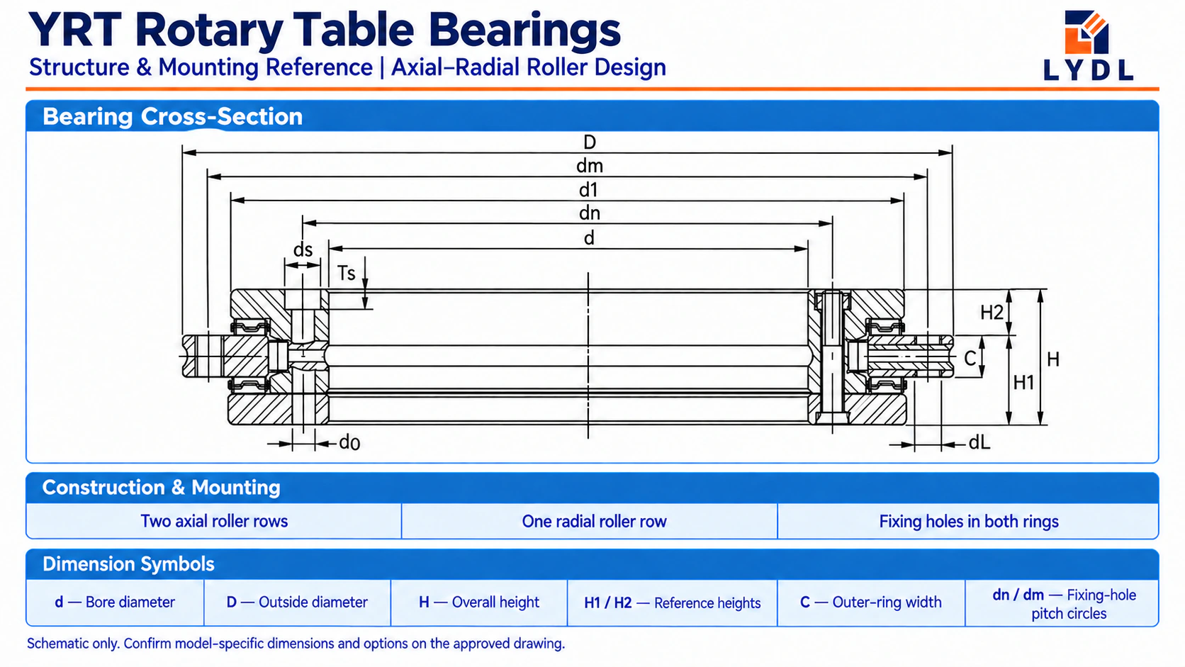
LYDL’s YRT/YRTS series table gives the following YRT100 boundary dimensions.
| Item | Published YRT100 dimension |
|---|---|
| Bore | 100 mm |
| Outside diameter | 185 mm |
| Height | 38 mm |
These values help identify the installation envelope. They do not define an allowable runout, the size of an inspection fixture or the final table accuracy. Put those requirements on the agreed inspection drawing.
Separate three kinds of accuracy
A supplier report and a customer inspection can disagree because they describe different surfaces or assembly states.
| Requirement | What the measurement concerns | Essential definition |
|---|---|---|
| Bearing running accuracy | A designated reference surface on the bearing in the specified fixture | Reference, rotating ring, supported condition and applicable limit |
| Finished-axis runout | Table face, locating pilot or test artefact after assembly | Datum scheme, assembled components, probe location and load |
| Angular positioning | Commanded angle versus measured angle | Measuring system, test procedure and positioning requirement |
An indicator on the table face does not directly measure encoder accuracy. Equally, a bearing inspection result cannot be used as the guaranteed runout of every face later attached to it.
For each required check, mark the actual surface on the drawing. Avoid a report field labelled only accuracy or runout.
Prepare the supported measurement condition
Schaeffler’s YRT-family fitting instructions specify checking running accuracy with the bearing fitted, screw mounted and fully supported. This explains why the loose bearing and the completed bearing position should not be treated as equivalent test states. Technical reference: MON 83 fitting instructions
For the supplied LYDL configuration, define the fixture and support requirements in the inspection agreement. Before measuring:
- Confirm the bearing and fixture drawing revisions.
- Verify that intended mounting contacts are seated and the approved fixing sequence is complete.
- Identify the fixed and rotating components.
- Stabilise the assembly and instrument for the agreed temperature condition.
- Check instrument identification, calibration status, probe orientation and repeatability.
- Record external load and any connected equipment.
The setup should make the indicator support and reference relationship visible. Instrument resolution alone is insufficient to describe the uncertainty of the complete method.
Place the probe where the requirement applies
For an axial-face measurement, specify the measurement-circle diameter. A reading close to the centre and a reading near the table edge may differ because of tilt and face form. Neither location substitutes automatically for the other.
For radial runout, specify the cylindrical surface and axial contact location. A reading near a locating shoulder and one at the end of a test artefact can include different effects from the assembly geometry.
| Check | State on the measurement plan |
|---|---|
| Axial face | Exact face, measurement-circle diameter, probe direction and reference |
| Radial cylinder | Exact cylindrical surface, axial contact location, probe direction and reference |
| Repeated rotation | Direction, speed, travel, repeat count and reporting rule |
| Assembly scope | Bearing fixture or completed table; components included |
Calculate TIR without changing what the test means
For one prescribed trace, total indicator reading is the largest indication minus the smallest. Mitutoyo describes the measurement as MAX minus MIN. A single trace does not automatically satisfy a drawing requirement for a more extensive geometrical inspection. Technical reference: measurement guide
The following is a calculation example, not an LYDL inspection report or a YRT100 accuracy specification.
| Illustrative trace | Maximum | Minimum | Calculated range |
|---|---|---|---|
| Rotation 1 | +8 µm | −2 µm | 10 µm |
| Rotation 2 | +7 µm | −2 µm | 9 µm |
| Rotation 3 | +8 µm | −2 µm | 10 µm |
For rotation 1: 8 − (−2) = 10 µm = 0.010 mm.
Keep the three trace results and the corresponding conditions. Do not average them merely to obtain a smaller acceptance value. The inspection agreement should specify how repeated measurements and measurement uncertainty enter the decision.
Also preserve the angular pattern when practical. Similar range values can have different patterns; a repeatable high point can guide further investigation without proving its cause.
Use a feature-by-feature acceptance sheet
The fields below form a blank inspection plan. Fill them with agreed requirements and actual results.
| Field | Entry required |
|---|---|
| Identification | Full bearing designation, unit/lot, drawing and fixture revision |
| Inspected feature | Surface ID on the drawing |
| Reference | Datum feature and indicator-support arrangement |
| Assembly | Fixed/rotating ring, support, fixing procedure and connected components |
| Probe position | Axial measurement-circle diameter or radial axial location |
| Conditions | Temperature, load, direction, speed and number of rotations |
| Equipment | Instrument ID, calibration status and method capability |
| Results | Maximum, minimum and range for each specified trace |
| Acceptance | Matching limit, reporting rule, uncertainty treatment and decision |
This plan can accompany an enquiry before any results exist. The acceptance limit should come from the agreed requirement, not from a value chosen after measuring the part.
If the reading exceeds the limit
First confirm that the surface, reference, probe location and limit match. A comparison between different measurement-circle diameters is not a controlled acceptance test.
Next check seating, indicator support, contact orientation and repeatability. Review the mounting record before attributing the result to the bearing. If the approved procedure calls for reassembly, retain the original record and repeat the inspection under the documented revised condition.
Do not combine an unverified mounting change and a new measuring setup in one step; that makes the reason for an improved or worsened result harder to establish.
Questions buyers should ask
What is the acceptable YRT100 runout?
There is no single value established by the model number alone. State the supplied configuration, measured feature and method, then agree on the applicable limit.
Does a higher bearing accuracy grade guarantee table positioning accuracy?
Bearing running accuracy, assembled runout and angular positioning are separate requirements. Define and verify each relevant requirement.
Can the acceptance procedure be agreed without a video?
Yes. A marked drawing, setup description and readable results provide the essential record. A video can help explain the setup when available.
Request the drawing and inspection scope together
Start with the LYDL YRT product range and the published YRT100 series entry. Send a marked drawing identifying the surfaces that control your acceptance decision, plus the mounting state and required limits.
Contact LYDL about YRT inspection requirements with the feature-by-feature plan. This makes the requested bearing inspection and the customer’s completed-table inspection easier to compare before the purchase specification is finalised.