If an RU crossed roller bearing becomes harder to turn after mounting, first compare its resistance before and after each assembly stage under the same test conditions. Check seating, supporting faces, screw engagement and contact with adjacent parts before changing the bearing specification. Hand feel alone cannot distinguish mounting distortion from preload, seals, grease or connected equipment.
This guide is for designers, assembly teams and buyers investigating a change introduced during installation. It provides a diagnostic sequence and a record you can use in a technical enquiry; it does not prescribe a universal acceptable torque.
First identify which torque changed
Three different quantities are often shortened to bearing torque.
| Quantity | Meaning | What must accompany the value |
|---|---|---|
| Bolt-tightening torque | Torque applied to a mounting fastener | Joint specification, screw grade, lubrication and engagement |
| Starting torque | Resistance when rotation begins | Dwell, direction, temperature, load and fixture |
| Running torque | Resistance during continued movement | Speed, direction, travel, lubricant, load and mounting state |
Record bearing-only resistance separately from the completed axis where the approved arrangement permits measurement. With a motor, cable carrier, seals or rotary connection attached, the result may include their resistance too.
Preload, lubrication, sealing and mounting conditions can influence rotational resistance. Schaeffler discusses these factors in its crossed roller bearing functional checks. Its guidance identifies possible influences, rather than a pass/fail limit for an LYDL bearing. Technical reference: functional checks

Locate the assembly stage that introduced the change
The most useful first question is: when did the resistance change?
Use the same bearing, measurement method and direction. Keep temperature, lubricant condition, dwell and test speed comparable. Secure and support the assembly for each permitted test; do not operate a loaded machine with loosened fixing screws.
| Stage | What to record | Interpretation to investigate |
|---|---|---|
| Incoming bearing in the agreed fixture | Starting and running resistance; conditions | Establishes the reference for later comparisons |
| First interface mounted | Resistance and angular pattern | A change here directs attention to that interface and its fixing |
| Both interfaces mounted | Resistance, angular pattern and specified runout | A further change directs attention to the second interface or assembled stack |
| Drive and accessories connected | Total axis resistance | Identifies resistance added by surrounding equipment |
This comparison narrows the investigation. A change after one stage does not, by itself, prove which feature caused it.
When comparing two readings, record the difference in N·m as well as the original values. A percentage change can exaggerate a small difference when the baseline is close to zero; consider the measurement capability and agreed acceptance limit.
Match the observation to a practical check
Use the following table to plan checks, not to diagnose a defect from a symptom alone.
| Observation | Possible factors to investigate | Practical next check |
|---|---|---|
| Resistance increases after the first interface is secured | Incomplete seating, locating fit, supporting-face error or unintended contact | Inspect that interface against the section drawing and record the supported condition |
| Resistance changes mainly during final tightening | Clamp distribution, screw engagement or deformation of supporting parts | Review screw length, usable thread depth, seating and the specified tightening sequence |
| A peak repeats at the same angular position | Local interference, geometry of the mounted assembly or a bearing-related issue | Mark the position and compare the resistance pattern with runout and contact observations |
| The increase appears after connecting the drive | Coupling, alignment, cable routing, seals or connected mechanisms | Compare the safely isolated bearing arrangement with the connected-axis measurement |
| Readings change as the assembly warms | Lubricant behaviour, thermal changes or a changing test condition | Record temperature and time; compare with the approved operating and test conditions |
For the mounting joint, check these details before selecting a different preload:
- Contact surfaces: cleanliness, burrs, raised edges and complete seating.
- Location: actual fit, locating diameter and the intended shoulders.
- Fasteners: length, thread engagement, bottoming clearance and screw-head seating.
- Adjacent parts: clearance to covers, shoulders, seals and rotating components.
- Assembly method: the specified sequence, calibrated tool and documented final joint condition.
THK’s assembly instructions describe progressive cross-pattern tightening. Use the procedure and joint values approved for the actual LYDL supply; a general screw-size table cannot define every material and mounting arrangement. Technical reference: crossed roller ring assembly
For RU124, confirm the mounting variant before investigating the joint
The LYDL RU124 product page distinguishes same-side counterbore access, opposite-side access and an inner-ring threaded version across RU124, RU124G and RU124X. A similar outside appearance can therefore conceal a different screw-access requirement.
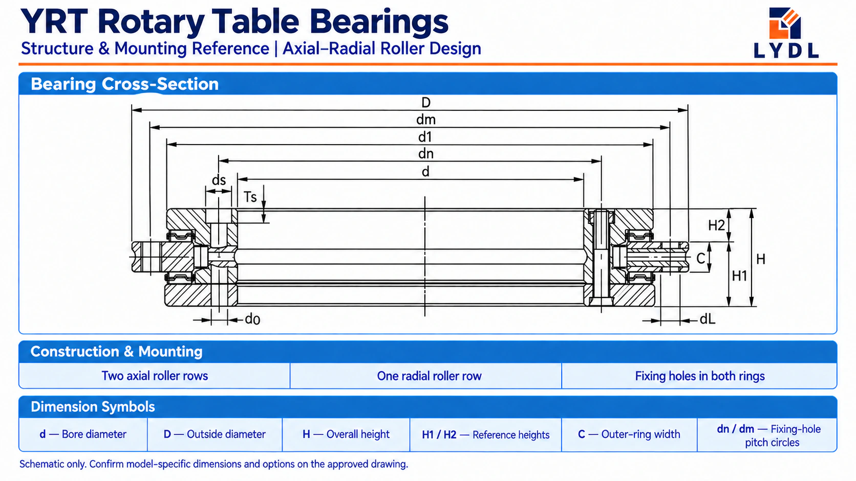
Compare the complete designation with the assembly section. Check which side the screw enters, which component contains the working thread and whether the selected length seats the joint correctly. For a threaded-ring version, do not assume a screw chosen for a through-hole arrangement will have suitable engagement.
This is an interface check. The suffix does not supply the machine’s tightening specification or prove that mounting caused the resistance change.
Use a record that separates observation from explanation
Copy this structure for the investigation. Empty fields are for actual measurements, not assumed results.
| Record item | Information to enter |
|---|---|
| Bearing identification | Complete model, suffixes, unit/lot identification and drawing revision |
| Configuration | Rotating ring, fixture, mounting stage and connected components |
| Conditions | Temperature, dwell, direction, speed/travel, lubricant and external load |
| Joint record | Screw specification, fixing sequence and approved tightening values |
| Measurements | Starting torque and running torque, with units and instrument identification |
| Pattern | Uniform resistance or repeatable peak; angular position if recorded |
| Related observations | Runout, noise, contact marks and temperature behaviour |
| Next action | One controlled change, responsible person and repeat-measurement conditions |
If rotation is rough or temperature rises unexpectedly, stop the inspection in accordance with the supplier’s procedure and preserve the observations. Raising drive torque to overcome an unexplained restriction can make the original change harder to investigate.
Questions to settle before accepting the bearing
Should an RU bearing turn freely by hand?
Hand rotation is an observation. A preloaded or sealed configuration can have noticeable resistance; acceptance requires the agreed configuration and measurement method.
Can loosening screws prove the bearing is defective?
A change with fixing condition points to an interaction worth investigating. It does not isolate the bearing, support surfaces and joint without further controlled checks.
Does a higher accuracy grade guarantee lower torque?
Specify running accuracy and rotational resistance separately. A grade label does not replace a torque requirement with stated conditions.
Send LYDL a defined mounting question
Use the LYDL RU series to identify the candidate model, then send the mounting section and the stage at which resistance changed. Include the rotating ring, full suffixes, test conditions and required starting/running torque or runout limits.
Contact LYDL about the RU mounting arrangement with the completed record. A documented before-and-after comparison gives both sides the same problem to investigate and a clearer basis for discussing the bearing configuration and inspection scope.