

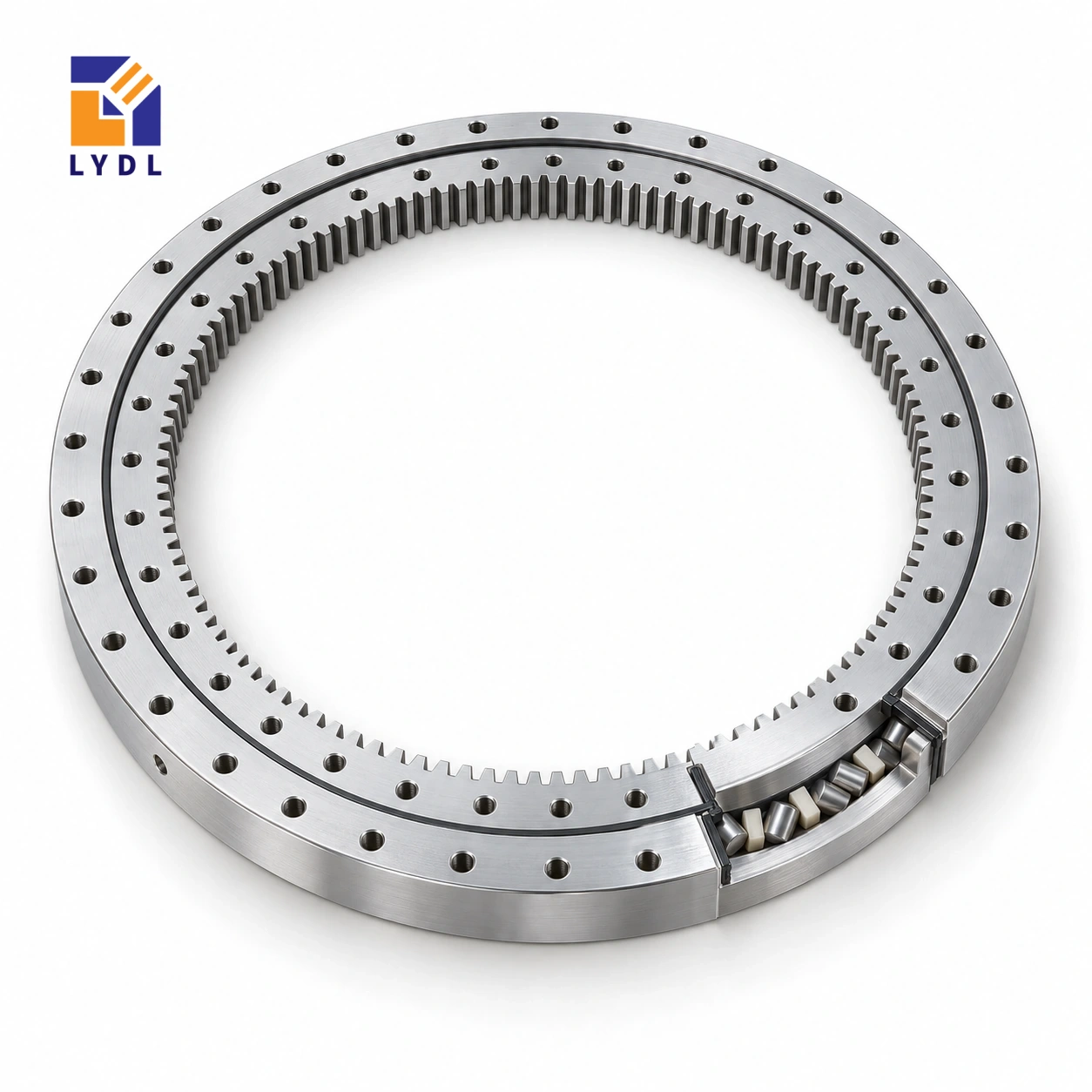
The XSI141094 internally geared slewing reference is listed with a 984 mm bore and 1164 mm outside diameter. Its 56 mm reference height, module 8 gear and 125 teeth define a large internally driven crossed roller arrangement for application review.
XSI141094: LYDL table; original height from Catalogue 404, pp. 84–85. Ordered execution requires drawing agreement.
XSI specification tables · Family technical reference
| Bore (mm) | Outside (mm) | Height H (mm) | Mass ≈ (kg) |
|---|---|---|---|
| 984 | 1164 | 56 | 91 |
| Outer PCD La (mm) | Inner PCD Li (mm) | Outer holes na | Inner holes ni |
|---|---|---|---|
| 1140 | 1055 | 48 | 48 |
| Pitch d0 (mm) | Module m (mm) | Teeth z |
|---|---|---|
| 1000 | 8 | 125 |
The approximate reference mass is 91 kg, excluding attached plates and drive components. Decide which parts are lifted together and which are assembled on the machine. Access around the 1000 mm gear pitch circle must accommodate the pinion and its support without obstructing the inner connection. A clear installation sequence also helps keep the ring protected until the surrounding structure is clean and ready.
Forty-eight fixing positions on each ring lie on 1140 mm and 1055 mm circles. Review screw-tool reach around the entire circumference and confirm the accepted centring execution before making the mating flanges.
Arrange unloading so the ring can remain supported while identification and agreed dimensional features are checked. Plan how wrapping is removed without exposing the internal teeth to loose blocking, screws or lifting hardware. Record any accessories separately from the ring and preserve the drawing revision that identifies its execution. Define the complete lifted mass for each installation step rather than relying on the approximate component figure.
At the machine, show the central equipment in the condition required to reach all forty-eight inner positions. The pinion and its bracket need an installation and withdrawal route in addition to their operating space. Review those paths before completing guards or fixed service connections. For application assessment, supply load positions and force directions with a clear reference to the ring plane.
Include maximum eccentricity, horizontal forces and braking events as distinct cases. State the required loaded behaviour at a useful platform datum. The 125-tooth entry defines only part of the transmission geometry; it does not state drive torque, positioning accuracy or a system load rating. Keep the supply drawing, mesh specification and equipment requirements together in the final review.
The XSI141094 gear row describes internal teeth with module 8 and 125 teeth. Their product is 1000 mm, matching the listed nominal pitch diameter. That arithmetic checks the relationship between three entries; it does not calculate a permissible tooth force. The physical outside diameter is 1164 mm and the bore is 984 mm, so neither should be replaced by the pitch-circle value in a clearance drawing. Overall height H is 56 mm. Locate the gear face and the two mounting planes from the offered section before positioning a pinion. The tooth form, engagement, quality requirement and supplied material execution remain separate specification items. Keeping these definitions distinct prevents a correct transmission number from being used as the wrong housing dimension.
The 984 mm nominal bore can appear generous until the stationary process body, internal pinion and their services are drawn together. Include collars, connectors, brackets and removal movements. Identify which parts rotate and how a fixed module is introduced through the assembled deck. Operating clearance and assembly access are different requirements.
Check the route for servicing the pinion and inner connection after the process equipment is installed. Establish a supported maintenance state for the deck. If an access opening is needed, show it in the actual flange section used for review. Avoid postponing these decisions until a late cutout or adapter changes the support arrangement.
Module 8 and the listed tooth count identify the nominal internal gear relationship. Specify the proposed mating pinion and its complete support before calculating the machine ratio or selecting a motor. Locate the tooth face from the offered section, not from total H alone. Include adjustment and the space required to inspect engagement.
Describe angular travel, acceleration, normal reversal and relevant stop conditions with the moving mass distribution. If a restraint carries process reactions while stopped, show where it acts. Neither the large pitch diameter nor the approximate 91 kg component mass establishes permissible torque or payload. The actual offered execution and complete equipment duty are needed for those questions.
The outer fixing circle is 1140 mm and the inner 1055 mm; each lists forty-eight positions. Keep both patterns dimensioned from defined equipment datums. Add the actual screw, seat, engagement and locating details from the supply drawing. Verify tool access with the internal transmission and central body in their installed states.
Review the manufactured backing beneath the annuli, including joints and pockets. Define the condition used for seating checks and the agreed installation procedure. A large support can still have a weakly backed sector, while a correct circle and count do not define the whole connection. Do not use tightening to make an uncertain interface fit.
Give the payload and tooling geometry with relevant force locations and heights. Include partial occupancy and process contact during dwell. Choose the installed observation datum and state the configuration under which the result is required. Movement at that datum can include the deck, joints, drive and bearing arrangement.
Agree component receiving checks separately from the completed-machine test. Keep approach direction, support and load state with each observation. Retain the accepted drive and flange revisions so a later tooling change can be evaluated against the same basis. A family designation or shared photograph does not supply a guaranteed accuracy for the assembled platform.
Attach the equipment section and operating schedule to the enquiry, along with requested quantity and evidence. Confirm the offered LYDL tooth, sealing and service execution on a controlled drawing. Original-reference and website data identify the nominal study basis; the accepted offer defines the purchased configuration.
Discuss handling, storage interval and protection of the machined interfaces during shipment. Keep loose process hardware away from the ring. Describe contamination and cleaning exposure for the service review. Preserve identity and revision after receipt so future spare orders refer to a defined component and installation rather than an assumed match based only on envelope dimensions.
XSA141094 places a module 8 gear outside a 1024 × 1198.1 × 56 mm envelope and lists 148 teeth. The present XSI row places 125 teeth inside a 984 × 1164 × 56 mm envelope. Their attachment data also differs, so these references represent different equipment layouts rather than two reversible drive positions.
Show the fixed central process body with each actual transmission concept. The internal mesh uses central room; the external alternative needs perimeter and guard space. Check installation and removal as well as normal movement. Select the arrangement that satisfies the real constraints, then resolve its LYDL drawing and operating assessment. Shared module and height do not establish an interchangeable completed assembly.
A large material-handling platform is a representative design example. Supply the worst eccentric payload, horizontal force at its operating height and transient loads from acceleration or stopping.

Agree receiving checks, reference datums and functional-test support conditions before delivery. Specify a rigid transport base and protection that keeps straps or blocking clear of internal teeth and sealing edges.

The nominal bore is 984 mm. Use the actual parameter table rather than reading the model suffix as the clear opening.
Module 8, 125 internal teeth and a 1000 mm pitch diameter are listed in the reference data.
Forty-eight positions per ring on 1140 mm and 1055 mm circles, with detailed screw and locating geometry from the accepted drawing.
No. It is the approximate reference bearing mass. Handling equipment must be chosen for the complete actual lifted assembly and approved method.
Include horizontal forces and their height, eccentric gravity loads, and acceleration or braking. These can produce different governing moments at the support.
Perimeter drive: XSA series. Separate-drive reference: XSU range.
Request XSI141094 with a lifting sequence, complete force diagram and module 8 pinion assembly.