

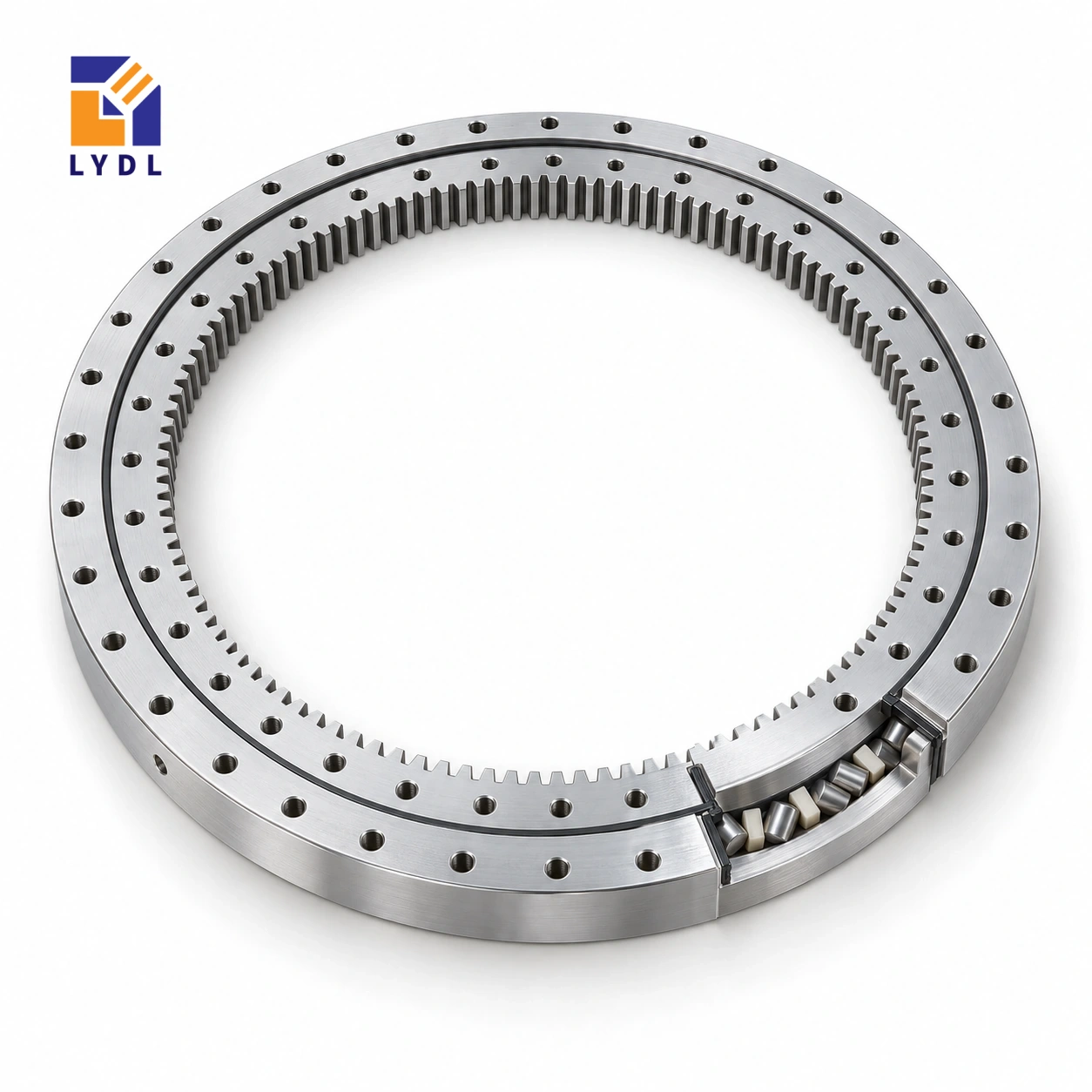
XSI140944 is an internal gear cross roller reference with an 840 mm bore, 1014 mm outside diameter and 56 mm height. The gear listing gives module 8, 107 teeth and an 856 mm pitch diameter.
XSI140944: LYDL table; original height from Catalogue 404, pp. 84–85. Ordered execution requires drawing agreement.
XSI specification tables · Family technical reference
| Bore (mm) | Outside (mm) | Height H (mm) | Mass ≈ (kg) |
|---|---|---|---|
| 840 | 1014 | 56 | 76 |
| Outer PCD La (mm) | Inner PCD Li (mm) | Outer holes na | Inner holes ni |
|---|---|---|---|
| 990 | 905 | 44 | 44 |
| Pitch d0 (mm) | Module m (mm) | Teeth z |
|---|---|---|
| 856 | 8 | 107 |
The reference uses forty-four fixing positions per ring. If a central equipment column is already installed, some of the inner screws may be difficult to reach even though the nominal bore is large. Model the tightening tool, pinion removal and inspection access before completing the platform enclosure. An access opening added later can weaken the annular support, so include any required cutouts in the structural review from the start.
The nominal fixing circles are 990 mm and 905 mm. Inspect seating faces after fabrication and before bringing the ring into place; do not expect the bearing connection to correct an uneven welded support.
Describe where cleaning liquid or process debris can reach the internal mesh and how the equipment enclosure directs it away. Identify drain paths, covers and the maintenance state in which they are removed. A bearing family name cannot establish that a packaging machine is cleanable or protected for a specific fluid. Agree the offered sealing and lubrication execution for the described environment.
Show the actual tool needed for the forty-four-position inner connection beside the feed column and pinion support. Consider removal of a screw as well as initial tightening, including the space to withdraw it. Any access cutout should appear on the structure drawing before assessment. For operating loads, distinguish filling or sealing reactions from movement of the product platform.
State permitted uneven occupancy and forces applied during recovery from a jam where relevant. The resulting enquiry connects environment, geometry and duty without inventing a certification or capability from the reference dimensions. Acceptance should use the specified delivered configuration and a clearly described machine commissioning condition.
The XSI140944 gear row describes internal teeth with module 8 and 107 teeth. Their product is 856 mm, matching the listed nominal pitch diameter. That arithmetic checks the relationship between three entries; it does not calculate a permissible tooth force. The physical outside diameter is 1014 mm and the bore is 840 mm, so neither should be replaced by the pitch-circle value in a clearance drawing. Overall height H is 56 mm. Locate the gear face and the two mounting planes from the offered section before positioning a pinion. The tooth form, engagement, quality requirement and supplied material execution remain separate specification items. Keeping these definitions distinct prevents a correct transmission number from being used as the wrong housing dimension.
The nominal envelope is 840 mm bore by 1014 mm outside diameter with 56 mm height. Draw it with the real upper plate, base and adapters to establish the working stack. Show the internal pinion and bracket within the central region, including their adjustment and removal movements. The outside perimeter can remain comparatively open while the centre becomes a service constraint.
If stationary process equipment passes through the bore, include its collars, connectors and temporary installation path. Decide which items are assembled first. Check whether the drive can be serviced without removing that equipment or the entire deck. These details should accompany a dimensional enquiry rather than be left until the component arrives.
The module 8 gear has a listed pitch diameter of 856 mm. Identify the proposed pinion, support bearings and reduction train before deriving machine movement from the 107-tooth count. A common module with a nearby reference does not preserve the ratio or guarantee acceptable engagement.
Describe the required angular motion, reversal and dwell with the moving inertia or its mass distribution. State any process holding reaction and the restraint used to carry it. For positioning, identify the output datum and the condition of observation. The ring's nominal gear row supplies geometry, while allowable forces, supplied tooth execution and installed behaviour require separate agreement for the actual machine.
Place the 990 mm outer and 905 mm inner fixing circles on the manufactured mating sections. Both list forty-four positions. Include actual screw seats, engagement and locating features from the supply drawing. Check access around the internal drive and any central equipment, including the path for withdrawing a screw.
Show local recesses, service windows and frame joints beneath the annuli. A concept drawn as a solid plate can misrepresent the backing present in the finished assembly. Define the support condition for seating measurement and the accepted fastening method. An installation should not rely on the ring to force an uncertain pilot or fabricated flange into conformity.
List tooling, parts and process forces at their real locations and heights. Include empty and partly occupied states if they occur. A lightly loaded but eccentric configuration can differ meaningfully from the heaviest centred one. Keep dwell forces and moving phases identifiable in the equipment schedule.
The observation at a tool near the edge includes plate deformation, joints, drive response and the bearing arrangement. Specify the required result there under a stated condition. The approximately 76 kg ring mass is component information for handling and cannot be read as a capacity rating. Provide enough machine context for the offered execution to be assessed against the intended task.
Request the LYDL drawing revision, applicable execution and agreed inspection information with the quotation. Compare constrained interfaces before machining. Record component identity at receipt and retain the flange and transmission revisions with commissioning observations.
Discuss the actual particles, liquids, cleaning and idle storage when defining protection and service access. Plan handling for the supplied ring using approved provisions and protect machined faces from loose hardware. Distinguish the generic inspection image from evidence requested for the ordered component. A future spare should be linked to this accepted configuration and operating record.
XSI141094 is the larger requested internal-gear reference at 984 × 1164 × 56 mm. It uses module 8 with 125 teeth and forty-eight positions per ring. This row is 840 × 1014 × 56 mm, with 107 teeth and forty-four positions. The common height keeps one axial entry familiar while changing the rest of the connection and transmission study.
For a wide process deck, draw the payload and central equipment on each candidate. Identify whether the larger opening is necessary and whether the base supports the revised circles. Include handling and pinion-maintenance space. Obtain the offered drawing for the retained arrangement; a larger family member does not automatically cover a changed process duty.
A packaging platform around a large stationary feed is one possible study. Describe washdown or cleaning conditions and product loading explicitly, since the reference dimensions establish neither hygiene design nor sealing suitability.

Request an agreed datum-based report and identify the supplied execution on the packing record. Keep hard accessories away from the internal gear during unloading and unpacking.

Forty-four positions per ring, on 990 mm outer and 905 mm inner fixing circles. Detailed angular locations remain drawing requirements.
It is the gear pitch diameter. The nominal bore reference is 840 mm, before accounting for installed drive and service components.
The reference uses module 8 and 107 internal teeth. Confirm tooth quality, backlash and engagement with the mating drive.
No. Define fluids, contamination and the enclosure design, then confirm the supplied sealing and lubrication configuration for those conditions.
Include them in the original assessment. Their location and extent can change flange stiffness and connection load distribution.
Perimeter drive: XSA series. Separate-drive reference: XSU range.
For XSI140944, include the inner-tool access model, feed-column geometry and cleaning environment.