

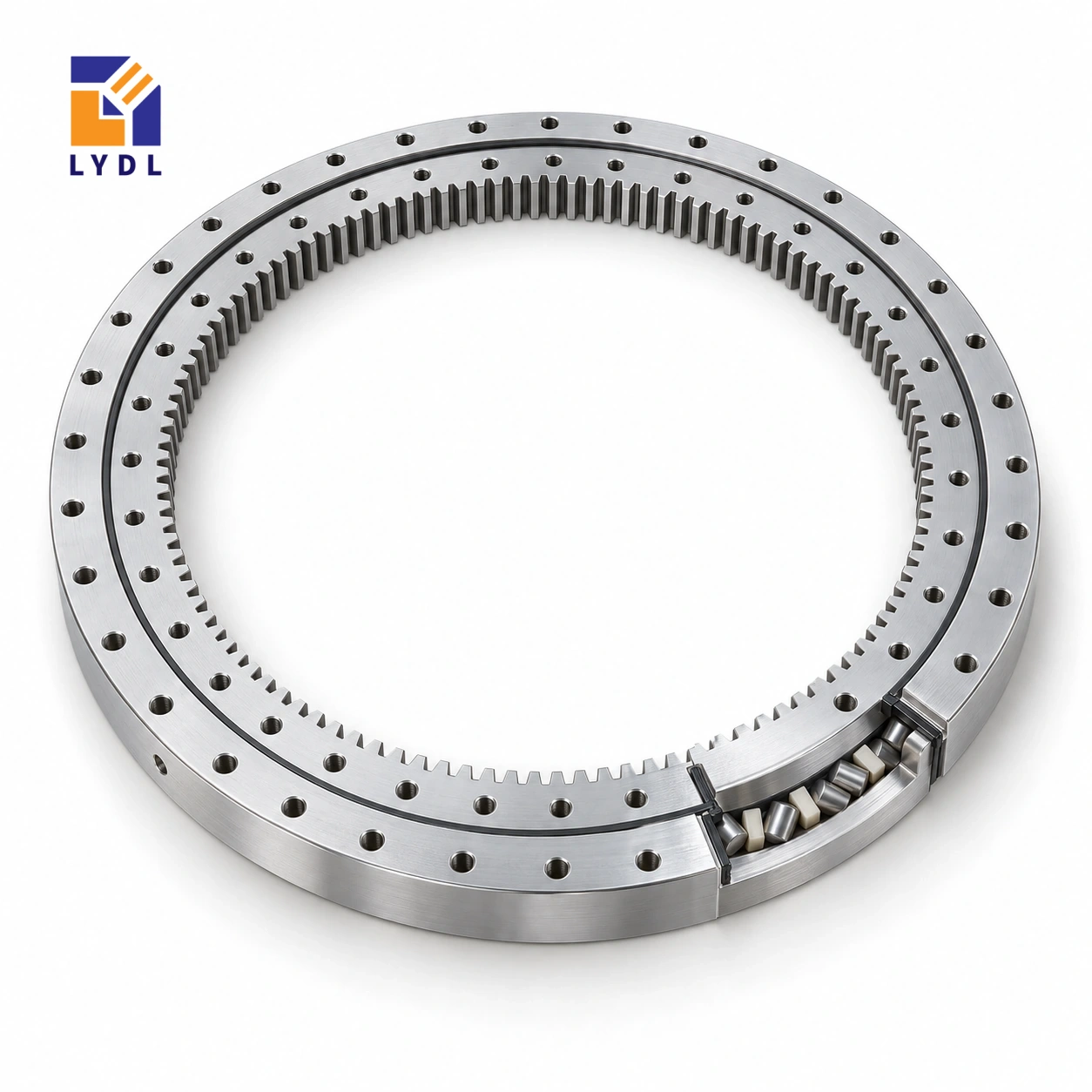
The XSI140844 internally geared bearing reference measures 736 × 914 × 56 mm. It introduces module 8 within this XSI group, with 94 teeth and a 752 mm pitch diameter, rather than continuing the module 6 arrangement of XSI140744.
XSI140844: LYDL table; original height from Catalogue 404, pp. 84–85. Ordered execution requires drawing agreement.
XSI specification tables · Family technical reference
| Bore (mm) | Outside (mm) | Height H (mm) | Mass ≈ (kg) |
|---|---|---|---|
| 736 | 914 | 56 | 69 |
| Outer PCD La (mm) | Inner PCD Li (mm) | Outer holes na | Inner holes ni |
|---|---|---|---|
| 890 | 805 | 40 | 40 |
| Pitch d0 (mm) | Module m (mm) | Teeth z |
|---|---|---|
| 752 | 8 | 94 |
The preceding XSI140744 reference has 110 teeth, whereas this larger reference has 94 because its listed module increases. Compare the full gear geometry and required ratio, not a simple tooth-count progression. Check whether a new pinion size changes the central service envelope or bracket load path. The bearing and fixing connections must still be assessed against the actual payload forces, duty and required system stiffness.
The fixing circles are 890 mm and 805 mm with forty positions per ring. Keep the pinion support, screw access and adjustment mechanism visible in a common section through the machine.
Prepare a centre-space drawing that includes the module 8 pinion, its supported shaft, adjustment travel and the service bundle. Compare it with the previous module 6 arrangement using actual component envelopes. The change can affect cable routing and removal access even when the external enclosure stays compact. Update the full transmission ratio before carrying over motor or encoder settings.
Define backlash and tooth-quality requirements with a measurable inspection method instead of interpreting the larger module as a performance class. For antenna tracking, describe the smallest normal movement, reversals, occasional slewing and periods of rest. Identify the environmental boundary provided by the surrounding enclosure and any wind loads that reach the support. These conditions belong in the application review; the dimensional listing does not establish an allowable exposure or pointing result.
Check the completed bearing connection and pinion bracket together after assembly, using the accepted drawing revisions. A consistent record of geometry, adjustment and measurement conditions makes later maintenance more meaningful than retaining only the model number and tooth count.
The XSI140844 gear row describes internal teeth with module 8 and 94 teeth. Their product is 752 mm, matching the listed nominal pitch diameter. That arithmetic checks the relationship between three entries; it does not calculate a permissible tooth force. The physical outside diameter is 914 mm and the bore is 736 mm, so neither should be replaced by the pitch-circle value in a clearance drawing. Overall height H is 56 mm. Locate the gear face and the two mounting planes from the offered section before positioning a pinion. The tooth form, engagement, quality requirement and supplied material execution remain separate specification items. Keeping these definitions distinct prevents a correct transmission number from being used as the wrong housing dimension.
XSI140744 uses module 6, while the present row specifies module 8 and 94 teeth. Both list 56 mm overall height. A familiar axial package therefore does not preserve the mating pinion, ratio or radial space needed by the transmission. Compare the actual drive sections before retaining a bracket or motor arrangement.
The present nominal pitch diameter is 752 mm. Locate it with the 736 mm bore and 914 mm outside envelope on the equipment layout, keeping the functions of those dimensions separate. Include pinion support, adjustment and removal space. Gear arithmetic checks the nominal row; the offered pairing still needs review for its real operating task.
Draw the fixed body with all protrusions and service movements. Add the internal drive and rotating deck through their full motion. Identify the passage needed to install connectors or withdraw a module, which may be greater than the operating clearance. A bare-ring bore should not be used as a guarantee of available assembly space.
Show which part carries each process force to the frame. Loads acting directly through a fixed central support differ from those carried by the rotating flange. Check whether the pinion bracket blocks an inner fastener or service point. Resolving these relationships early can avoid an adapter or cutout that changes the reviewed support later.
Provide tooling and payload locations with their vertical and radial offsets. Include partially loaded states and process forces during dwell. Describe motion with the mass distribution, angular travel and timing. A single total weight cannot distinguish the important cases for a large annular station.
Choose an installed observation at a useful working datum and state the load and drive condition. The supporting plate, joints and transmission affect that result along with the bearing arrangement. The approximately 69 kg component mass assists handling planning; it provides no permissible payload, stiffness value or precision grade. Ask for application review against the actual machine requirement.
The outer attachment lies on an 890 mm circle and the inner on an 805 mm circle. Both list forty positions, but their mating parts need separate dimensions and locating details. Add screw form, seat and engagement from the offered drawing. Check tools and screw withdrawal with the fixed central body and drive assembled.
Show flange backing beneath the complete patterns, including local pockets and frame connections. Define the support state for seating inspection and the intended installation sequence. A broad flange can still contain a locally interrupted region. Fastener count alone cannot establish the adequacy of that joint or justify using tightening to correct a distorted seating.
Attach the machine layout, operating cases and requested inspection scope to the enquiry. Confirm the offered tooth, seal and service arrangement on the accepted LYDL drawing. Reference geometry and family photographs help identify the study basis but do not define every detail of the supplied ring.
Keep received-component checks separate from the loaded machine observation, with conditions recorded for each. Discuss contamination, cleaning and storage protection. Retain the actual pinion and flange revisions with the bearing identity so a future spare request can preserve the reviewed configuration even if the production tooling has changed.
XSI140944 increases the bore to 840 mm and outside diameter to 1014 mm from 736 mm and 914 mm here. Height remains 56 mm and module remains 8, but the tooth count rises from 94 to 107 and the fixing count from forty to forty-four per ring.
Compare the stationary central body and its removal route in both openings. Show the larger flange's actual support and the revised pinion relationship. A retained deck level may be convenient while nearly every radial interface changes. Select the candidate for a defined equipment constraint, then request the corresponding supplied execution with the force locations and motion attached. The numerical progression alone cannot decide capacity or installed accuracy.
An antenna positioning platform is an illustrative use study. Describe wind loading, low-speed tracking motion, reversals and cable management without assuming an environmental rating from the bearing family.

Agree gear checks for the module 8 mesh and reference the accepted drawing on the inspection record. Use stable shipping support with protection against bore-side impacts.

Its module is 8 rather than the module 6 of XSI140744. Read tooth count together with module and pitch diameter.
The nominal bore is 736 mm within a 914 mm outside diameter; the cited height is 56 mm.
Both references list forty positions per ring, but XSI140844 moves the circles to 890 mm and 805 mm.
Do not assume compatibility. A module change calls for a new detailed mesh and drive-layout review.
Provide wind-force cases, tracking and slewing cycles, pointing requirements, temperature exposure and the cable arrangement of the complete platform.
Perimeter drive: XSA series. Separate-drive reference: XSU range.
Send XSI140844 requests with pinion dimensions, target drive ratio and the central cable-clearance drawing.