

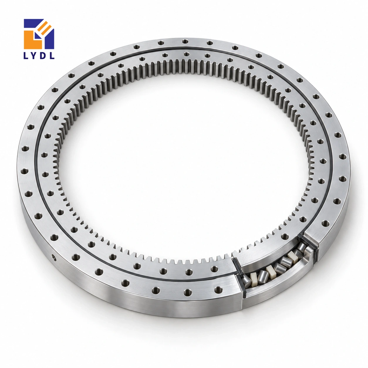
XSI140544 is an internally geared cross roller reference measuring 444 × 614 × 56 mm. It uses a module 6, 76-tooth gear listing, with thirty-two fixing positions on each ring and a 456 mm pitch diameter.
XSI140544: LYDL table; original height from Catalogue 404, pp. 84–85. Ordered execution requires drawing agreement.
XSI specification tables · Family technical reference
| Bore (mm) | Outside (mm) | Height H (mm) | Mass ≈ (kg) |
|---|---|---|---|
| 444 | 614 | 56 | 43 |
| Outer PCD La (mm) | Inner PCD Li (mm) | Outer holes na | Inner holes ni |
|---|---|---|---|
| 590 | 505 | 32 | 32 |
| Pitch d0 (mm) | Module m (mm) | Teeth z |
|---|---|---|
| 456 | 6 | 76 |
A higher tooth count changes the nominal transmission relationship only when the mating pinion is also specified. Confirm the complete ratio and tooth geometry before transferring a motor or encoder setting from another platform. Allow physical space for backlash adjustment and subsequent inspection inside the ring. The central drive can simplify the outside enclosure while creating access constraints around a fixed feed tube or service column.
Draw the 590 mm outer and 505 mm inner fixing circles beside the pinion bracket. Check whether the bracket is installed before or after the inner screws, and preserve the required tool reach in both cases.
Record the ring and pinion tooth counts together with every additional gearbox stage. Only then relate motor motion to the output platform. Define whether the application needs absolute station position, repeatability after approaching from one direction or controlled movement after reversal. These are different system behaviours, influenced by transmission clearance, structure and controls as well as the bearing.
On a packaging platform, identify the product-transfer datum and the permitted loaded condition for measuring it. Include feed-column supports and guards in the internal-space study. A pinion that fits during initial assembly may become inaccessible after those parts are installed. Decide which parts can be detached for routine mesh inspection without loosening the ring.
Draw the adjustment and locking mechanism clearly enough that the accepted setting can be reproduced. The thirty-two inner fixing positions also need their own tool-access check. Complete these equipment details before treating the nominal envelope as a finished installation design. They provide a more useful basis for the enquiry than a desired accuracy value with no measurement point or operating condition.
The XSI140544 gear row describes internal teeth with module 6 and 76 teeth. Their product is 456 mm, matching the listed nominal pitch diameter. That arithmetic checks the relationship between three entries; it does not calculate a permissible tooth force. The physical outside diameter is 614 mm and the bore is 444 mm, so neither should be replaced by the pitch-circle value in a clearance drawing. Overall height H is 56 mm. Locate the gear face and the two mounting planes from the offered section before positioning a pinion. The tooth form, engagement, quality requirement and supplied material execution remain separate specification items. Keeping these definitions distinct prevents a correct transmission number from being used as the wrong housing dimension.
Draw the cable or fluid route through the 444 mm opening along with the pinion shaft and bracket. Include connector bodies, restraints and the movement of any flexible segment. The bare-ring opening does not establish that a routed service remains clear through the machine's full motion or can be replaced after assembly.
Identify whether each line rotates, remains stationary or passes through a rotary interface. Show the temporary route used to fit it. Access for the inner fasteners and pinion adjustment should be checked with these services installed. Settling this layout early avoids a later opening or bracket change that alters the support previously reviewed for the ring.
The outer fixing circle is 590 mm and the inner is 505 mm, with thirty-two positions listed on each ring. Define their angular orientation relative to the pinion bracket and service outlet. Add the actual screw engagement and locating features once the offered drawing is available. A shared count does not remove the need for separate mating dimensions.
Check the supporting material beneath the full annuli, including recesses around cables and the motor. State the manufactured condition in which seating geometry is inspected. A substantial plate with a local access pocket can behave differently from the uniform section shown in an early concept. Keep the final geometry in the application and connection review.
Module 6 and 76 teeth correspond to the listed 456 mm pitch diameter. Specify the mating pinion and the full drive train for the intended movement. A common module with another XSI size does not preserve the same output angle per motor revolution. Include the actual shaft support and bracket when discussing engagement.
Describe normal indexing and reversal, the mass distribution being accelerated and any holding reaction during the process. If a brake or restraint is involved, show where its force enters the assembly. Define the result at the workpiece under a stated condition. These inputs allow review of a real transmission without deriving an unsupported torque capacity or positioning guarantee from the gear row.
List the permitted nests and their part positions, including empty and partly loaded conditions. A similar total weight can create different inertia or overturning effects when its location changes. Show the relevant force heights and any reactions from clamps or transfer guides. Keep stationary process cases distinct from the motion sequence.
For acceptance, choose a repeatable nest and measurement datum. Record the installed support and drive settings with the result, separately from received-component checks. A later nest change can then be compared against an explicit operating record instead of assumed to be covered merely because the bearing model stays the same.
Send the mating parts, service layout and duty with the enquiry. Confirm the offered tooth, seal and lubrication arrangements on the accepted LYDL drawing. Original-reference height information and the nominal website geometry identify the study basis; they do not replace the order-specific execution.
Discuss cleaning, contamination and storage before defining protection and inspection evidence. Preserve component identity and drawing revision after receipt. The approximately 43 kg listed mass assists handling planning, while the shared images provide family and application context. Neither a photograph nor that mass establishes the capability of the completed platform.
XSI140644 has a 546 mm bore and 714 mm outside diameter, compared with 444 mm and 614 mm here. Both are 56 mm high and module 6, but the larger row has 93 teeth rather than 76 and thirty-six positions per ring rather than thirty-two.
For the service layout, compare the actual connector and pinion-removal paths inside both rings. The additional opening may be useful, but it also changes the attachment circles and platform support. A common module does not preserve movement per pinion revolution. Resolve the proposed drive and LYDL execution with the selected machine section, keeping the motion and nest configurations in the enquiry rather than assuming that dimensional proximity answers the application question.
A packaging carousel around a stationary product feed is one representative layout. Include filling forces during dwell and the radial mass distribution during indexing, rather than giving only finished-product weight.

Discuss the agreed gear measurement scope and supported rotation check. Pack the ring so its internal mesh is isolated from loose drive components and fittings.

The reference uses module 6 with 76 internal teeth and a 456 mm pitch diameter.
No. This size lists 590 mm and 505 mm fixing circles with thirty-two positions per ring, plus a larger overall envelope.
The nominal bore is 444 mm. Subtract the space occupied by the internal drive and actual installed connection when checking usable clearance.
Specify the mating pinion and full transmission first. Tooth count by itself does not define the complete output ratio.
The drive bracket and feed column may block tools after assembly. A clear sequence avoids cutting access openings into a finished support plate.
Perimeter drive: XSA series. Separate-drive reference: XSU range.
Provide XSI140544 with the proposed drive ratio, feed-column envelope and assembly sequence.