

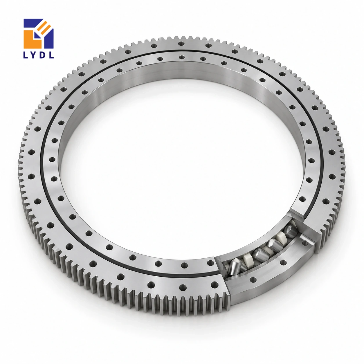
XSA140744 is an externally geared cross roller slewing bearing reference with a 674 mm bore, 838.1 mm outside diameter and 56 mm height. The gear listing uses module 6 and 138 teeth, extending the pitch circle to 828 mm.
XSA140744 reference dimensions: Catalogue 404, pp. 82–83; LYDL gear listing. Confirm the actual supply drawing.
XSA specification tables · Family technical reference
| Bore (mm) | Outside (mm) | Height H (mm) | Mass ≈ (kg) |
|---|---|---|---|
| 674 | 838.1 | 56 | 59 |
| Outer PCD La (mm) | Inner PCD Li (mm) | Outer holes na | Inner holes ni |
|---|---|---|---|
| 785 | 698 | 36 | 40 |
| Pitch d0 (mm) | Module m (mm) | Teeth z |
|---|---|---|
| 828 | 6 | 138 |
At this diameter, a platform can place much of its moving mass far from the rotation axis. Provide the radial mass distribution when asking for a drive and support review. Compare acceleration and deceleration cases separately from static eccentric loading. The tooth count helps define transmission kinematics, but it does not determine motor sizing without the complete ratio, losses, inertia and operating cycle.
Thirty-six outer positions lie on a 785 mm circle and forty inner positions on a 698 mm circle in the original reference. Check tool reach and clearances around the external drive bracket before making the final plate.
Draw the carousel stations at their actual radii and list fixture and product masses separately. Indicate which stations can be empty simultaneously and whether loading occurs while another station is processing. The governing inertia and eccentric force cases may belong to different occupancy patterns. Give the programmed motion profile and any distinct stopping condition.
A bearing proposal can then be considered alongside the transmission, rather than treating the 138-tooth entry as a motor-sizing input on its own. Place stationary tool reactions on the same layout with their directions and contact points. A press or clamp operating during dwell can govern a different part of the assembly from the indexing drive. Include the top-plate and base sections so their force paths are visible.
Define what the equipment must achieve at a working datum and how that result will be checked after assembly. This makes station performance an explicit system requirement instead of an unsupported property assigned to the ring.
The XSA140744 gear row describes external teeth with module 6 and 138 teeth. Their product is 828 mm, matching the listed nominal pitch diameter. That arithmetic checks the relationship between three entries; it does not calculate a permissible tooth force. The physical outside diameter is 838.1 mm and the bore is 674 mm, so neither should be replaced by the pitch-circle value in a clearance drawing. Overall height H is 56 mm. Locate the gear face and the two mounting planes from the offered section before positioning a pinion. The tooth form, engagement, quality requirement and supplied material execution remain separate specification items. Keeping these definitions distinct prevents a correct transmission number from being used as the wrong housing dimension.
Describe the carousel at the stages that actually occur: empty, partly occupied, fully occupied and transferring a part. Show fixture positions and the mass distribution of the moving deck. The most eccentric condition may occur between stations rather than at full occupancy. Keep it in the operating schedule with the relevant acceleration and dwell.
Include transfer-guide, clamp and process reactions with their locations. A part moving onto the deck can impose a different case from the same part resting on it. For an abnormal stop or recovery action included in the machine specification, describe the real sequence instead of assigning an unexplained generic overload. These details make an application review more useful than a single payload figure.
Place the stationary feed and central services through the nominal bore. Include connector removal, hose restraints and the tools needed at the inner flange. Define which items rotate and which remain fixed. A line routed through the opening may still interfere with a moving bracket or block a screw withdrawal path.
Plan the order of installing the ring, feed and upper deck. State how the deck is supported during a future bearing change and which surrounding modules must be detached. Keep those temporary conditions visible in the assembly instructions. Avoid late access slots that alter the supporting annulus without a corresponding structural review.
This external mesh uses module 6 and an 828 mm pitch circle. Show the pinion assembly beyond the listed 838.1 mm ring envelope, including the guard and bracket adjustment. Identify the proposed pinion geometry and its shaft support. The tooth-count relationship belongs to the transmission design; it does not establish allowable acceleration or torque by itself.
State any requirement to approach stations from both directions and locate the output observation at the product fixture. The complete carousel includes drive compliance, joints and platform deformation. Ask for an agreed supplied execution and a meaningful installed test instead of treating the bearing designation as a guaranteed positioning result.
The 785 mm outer circle lists thirty-six positions, while the 698 mm inner circle lists forty. Keep the two sets distinct on the base and moving deck. Add the actual screw form, seat, engagement and locating details from the accepted drawing. Check the full circumference for interference with feed equipment and the motor support.
Review the actual flange sections beneath both patterns. Large service windows, pockets or joints can affect local backing even where the overall deck looks substantial. Define the geometry-check state for the manufactured seating and follow the agreed installation method. The component should meet a prepared interface rather than be used to force a distorted platform into shape during tightening.
Submit the occupancy cases, motion schedule and mating drawings with the model enquiry. Agree the receiving inspection separately from the completed-line observation. Keep tooling, feed and drive revisions with the commissioning record so later production changes can be reviewed against the same configuration.
Describe dust, product fragments, cleaning and idle storage when discussing protection and service access. Request suitable shipment support for the approximately 59 kg component and separate loose feed hardware from its machined surfaces. The reference images explain the family and possible tasks, but do not document testing of XSA140744 or establish a capacity for the proposed line.
XSA140844 enlarges the nominal opening from 674 to 774 mm and outside envelope from 838.1 to 950.1 mm. The listed height stays 56 mm and the attachment counts stay thirty-six outer and forty inner, but the circles change. Its module 8, 117-tooth gear also differs from the module 6, 138-tooth row here.
For the carousel, compare the station layout and feed-removal route before changing size. Equal hole counts cannot justify retaining the same plate, and common height cannot justify retaining a pinion. Put the actual occupancy and transfer cases in the selected drawing enquiry. The larger nominal envelope is an alternative layout, not evidence that an undefined production duty is acceptable.
A multi-station assembly carousel is a representative study. Describe the most uneven station occupancy as well as any tool forces applied while the carousel remains stopped.

Agree the reference datum and support condition for dimensional checks. Secure the ring for transport on a stable base, protecting teeth and mounting faces from adjacent tooling.

It is 838.1 mm. The 828 mm value is the gear pitch diameter, and the bore reference is 674 mm.
Module 6 is listed with 138 external teeth. Pinion geometry and permissible engagement conditions require confirmation.
No. The original reference lists thirty-six outside and forty inside, on 785 mm and 698 mm circles.
Use the complete rotating assembly and its mass distribution. The approximate 59 kg reference bearing mass is not the platform inertia.
Include the most eccentric permitted occupancy and process-force combination, not only a fully filled balanced table.
Internal mesh: XSI series. Gearless alternative: XSU range.
For XSA140744, supply station masses, radial positions and the acceleration-time profile.