

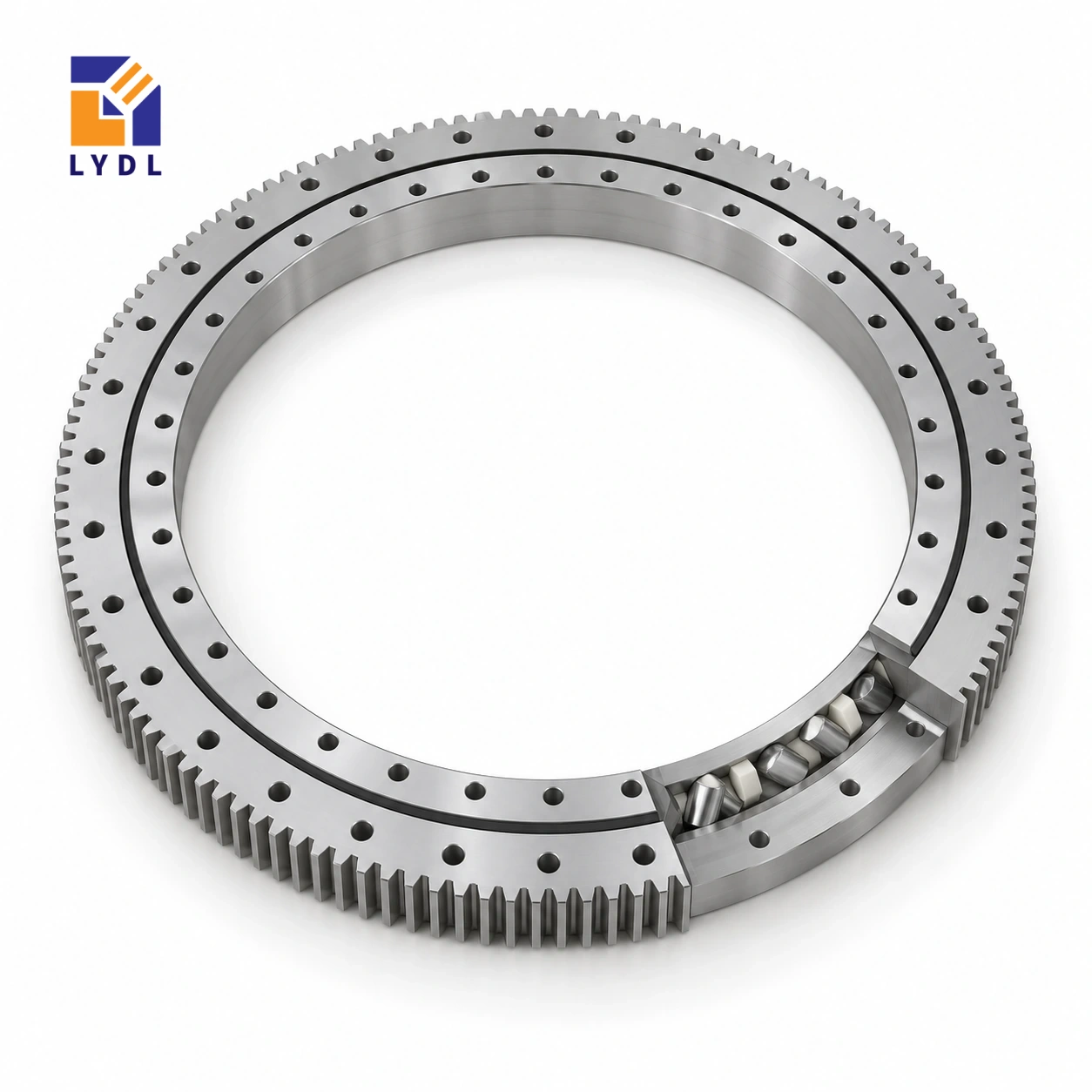
XSA140544 is an externally geared crossed roller reference with a 474 × 640.3 × 56 mm envelope. The gear entry gives module 6 and 105 teeth, while the ring fixing patterns use different counts on the inner and outer connections.
XSA140544 reference dimensions: Catalogue 404, pp. 82–83; LYDL gear listing. Confirm the actual supply drawing.
XSA specification tables · Family technical reference
| Bore (mm) | Outside (mm) | Height H (mm) | Mass ≈ (kg) |
|---|---|---|---|
| 474 | 640.3 | 56 | 44 |
| Outer PCD La (mm) | Inner PCD Li (mm) | Outer holes na | Inner holes ni |
|---|---|---|---|
| 585 | 498 | 28 | 32 |
| Pitch d0 (mm) | Module m (mm) | Teeth z |
|---|---|---|
| 630 | 6 | 105 |
Compared with XSA140414, this reference changes from module 5 to module 6 and moves the pitch circle from 495 mm to 630 mm. A pinion and bracket sized for the smaller ring cannot be assumed to suit this mesh. Check tooth form, shaft support, centre adjustment and the physical guard envelope together. Separately, compare the platform force diagram with the agreed bearing execution; a transmission-size increase does not quantify a raceway capacity increase.
The reference uses twenty-eight outer positions on a 585 mm circle and thirty-two inner positions on a 498 mm circle. Retain the distinction when reviewing screw access and the complete tightening sequence.
Before selecting the larger reference, record which station interfaces must stay at their present locations: working height, product-transfer centreline and any fixed feed. Overlay the proposed ring, pinion and support bracket on that layout. The module change means the previous drive cannot be retained solely because its motor power seems adequate. Request review of the complete transmission geometry and duty, including acceleration of the occupied carousel.
Count inner and outer fasteners independently when checking assembly time and tool reach. Consider whether a product guide or sensor bracket blocks one of the thirty-two inner locations after final assembly. For acceptance, state whether the concern is repeatable station presentation, loaded angular displacement or rotation resistance. Those results are measured under different conditions.
A well-defined equipment requirement helps separate bearing selection from transmission adjustment and upper-plate stiffness. Finish the comparison with one accepted supply drawing instead of combining nominal dimensions and tolerances from several references.
The XSA140544 gear row describes external teeth with module 6 and 105 teeth. Their product is 630 mm, matching the listed nominal pitch diameter. That arithmetic checks the relationship between three entries; it does not calculate a permissible tooth force. The physical outside diameter is 640.3 mm and the bore is 474 mm, so neither should be replaced by the pitch-circle value in a clearance drawing. Overall height H is 56 mm. Locate the gear face and the two mounting planes from the offered section before positioning a pinion. The tooth form, engagement, quality requirement and supplied material execution remain separate specification items. Keeping these definitions distinct prevents a correct transmission number from being used as the wrong housing dimension.
Locate the fixed column, rotating deck and external drive in a common section. Show collars, connectors and removable process modules rather than representing the column as a simple cylinder. The 474 mm bore is the basic opening reference, but assembly and maintenance can require a larger temporary route.
Decide which components are installed first and whether the column can be serviced without disturbing the ring. Check access to the inner connection with the column in place. Include the platform's force paths: a process reaction that goes directly through the fixed column differs from a reaction carried by the rotating deck. This distinction helps define the actual duty presented to the bearing and its mating structures.
The 585 mm outer fixing circle lists twenty-eight positions; the 498 mm inner circle lists thirty-two. Keep the counts tied to their own rings throughout drawing preparation, inspection and assembly. A copied pattern can look orderly in plan while failing the actual interface. Add the agreed screw seats, engagement and locating details before releasing machining.
Inspect the flange sections beneath both patterns for pockets, joints and service openings. Identify the support condition used for dimensional checks. Confirm that tools can reach every required location after the column, motor bracket and guard are fitted. If an access opening is introduced later, include its effect in the support review instead of treating it as a purely cosmetic change.
The nominal transmission geometry is module 6, 105 teeth and 630 mm pitch diameter. Show the proposed pinion's complete support, including its bracket and adjustment. The 640.3 mm listed outside envelope describes the ring; the assembled drive and guard extend beyond it. Preserve space for removing the motor and observing the mesh.
Describe indexing, normal reversal and holding during the process as distinct operating phases. Include the moving mass distribution and force locations. A common module with another reference does not establish an equal ratio or allowable drive load. Ask for assessment of the actual pairing and supplied tooth execution, with any required output observation stated at the machine's working datum.
XA140540 has the same listed outside diameter and module 6, 105-tooth gearing, yet its 471 mm bore and 48 mm H differ from the 474 mm bore and 56 mm H here. The fixing interfaces also require individual comparison. Matching transmission entries do not make the entire ring a drop-in substitute.
For a retrofit, mark the preserved machine datums and show the existing flange stack. Resolve tooth-face position, screw access and locating features through the offered drawing. Record the accepted identity rather than blending the two designations in procurement. This is particularly useful where the central column fixes the available opening and neighbouring equipment fixes the working height.
Agree component receiving features and the separate loaded observation of the completed station. For the latter, identify the column state, platform tooling and approach direction. Keep the configuration with the commissioning result so a later process change can be assessed against the same basis.
State the expected dust, liquid and cleaning exposure when discussing the offered protection. Request packing suitable for the machined seating and tooth perimeter, with loose column hardware separated. Preserve drawing and inspection records with the approximately 44 kg component's identity. The application montage communicates possible equipment tasks and does not supply proof of suitability for this specific installation.
XSA140644 increases bore from 474 to 574 mm and outside envelope from 640.3 to 742.3 mm. It retains the 56 mm height and module 6, yet changes the tooth count from 105 to 122. The attachment patterns grow from twenty-eight/thirty-two outer/inner positions to thirty-two/thirty-six.
For the fixed-column assembly, compare the column's collar and replacement path on both drawings. Confirm whether the extra opening solves the actual service obstruction. The wider flange and changed ratio still require individual support and pinion review. A geometric shortlist should lead to the offered LYDL section with the column and deck duties attached; it does not approve a substitution by family name.
A packaging turntable with an external drive is a representative layout. Describe loaded stations, acceleration and filling forces during dwell, as these enter different parts of the cycle.

Specify the tooth and mounting-datum checks that matter to the assembly. Separators and supported restraint should prevent contact between the external gear and other packed machine parts.

No. This reference uses module 6 with 105 teeth; XSA140414 lists module 5 with 99 teeth.
The original reference gives twenty-eight outside and thirty-two inside, on 585 mm and 498 mm circles respectively.
The reference envelope is 474 mm bore, 640.3 mm outside diameter and 56 mm height. The approximate reference mass is 44 kg.
Check guarding during layout. Its removal path and clearance around the pinion may affect machine width and maintenance access.
No. Preload and running requirements must be defined for the actual supplied execution; this page does not turn original reference values into delivery promises.
Internal mesh: XSI series. Gearless alternative: XSU range.
Send the module 6 pinion layout and loaded-station cycle with the XSA140544 drawing request.