

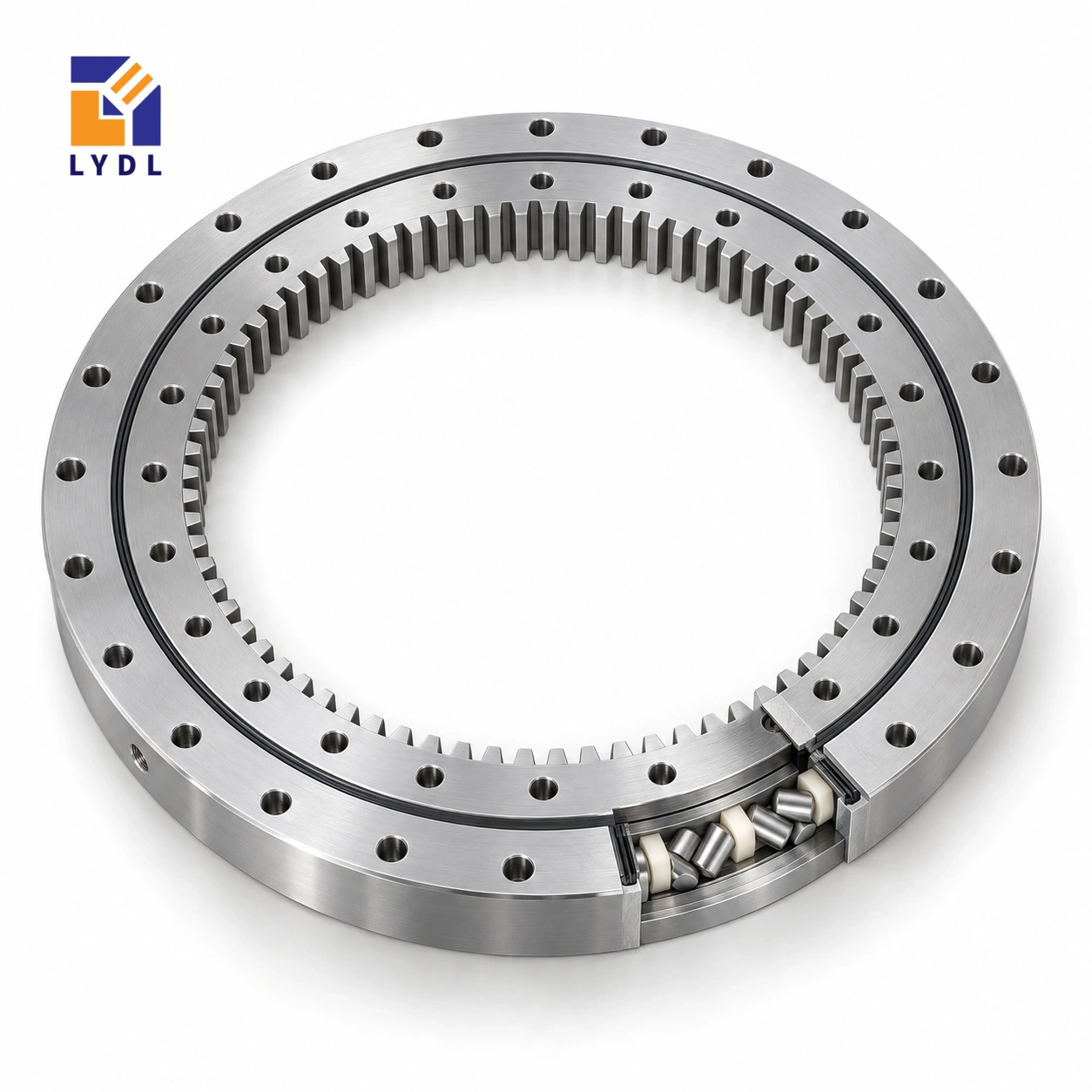
The XI201100 internally geared slewing bearing is a large LYDL crossed roller listing with a 950 mm bore and 1200 mm outside diameter. Its 70 mm overall height, module 10 gear and thirty-position fixing patterns call for careful handling and installation planning.
XI201100: nominal LYDL listing. INA interchange unverified. Supplied execution requires an agreed drawing.
XI specification tables · Family technical reference
| Bore (mm) | Outside (mm) | Height H (mm) | Mass ≈ (kg) |
|---|---|---|---|
| 950 | 1200 | 70 | 150 |
| Outer PCD La (mm) | Inner PCD Li (mm) | Outer holes na | Inner holes ni | Hole dB (mm) | Secondary h (mm) |
|---|---|---|---|---|---|
| 1160 | 1040 | 30 | 30 | 22 | 54 |
| Pitch d0 (mm) | Module m (mm) | Teeth z | Width b (mm) |
|---|---|---|---|
| 970 | 10 | 97 | 60 |
Establish the lift path, temporary supports and access to the inner connection before the ring is delivered. Approximate listed bearing mass is 150 kg, excluding the fixture and drive components, so handling must be designed for the complete lifted assembly. Keep lifting forces away from the internal gear, seals and unapproved attachment points. The 970 mm pitch circle also needs room for the drive system inside the nominal opening.
The listed fixing circles are 1160 mm and 1040 mm with thirty positions per ring. Preserve the 70 mm overall-height entry independently of the 54 mm secondary height and 60 mm gear width in the table.
Prepare a route drawing from the unloading position to the completed machine. Include doorway clearance, turning space and the proposed temporary support location. Establish the actual lifted mass for each assembly step and use a handling method approved for that configuration. The component mass in the table cannot account for plates or a motor installed before lifting.
Protect the internal teeth from contact with transport blocking and identify which surfaces may be used for support. Arrange receiving inspection while the ring remains stably supported, with access to its identification and the agreed measurement features. For the machine layout, separate nominal bore space from the volume required by the module 10 pinion, bracket and adjustment travel. A large opening can still leave an awkward inner connection if a central column is fitted too early.
Review all thirty inner positions for tool access and plan how the pinion is withdrawn. On an antenna platform, request the environmental and operating cases individually, including idle exposure and active positioning. The page provides reference geometry; the wind-load capability, movement limits and pointing result require assessment of the complete offered system. Record the agreed drawing revision before manufacturing the surrounding interfaces.
For a remote installation, decide which receiving records can be produced before the ring leaves the dispatch area and which checks require the destination machine. Identify the responsible equipment datum for each. Photograph markings and packaging condition as receiving evidence, while keeping dimensional and functional measurements in their own records. A photograph can identify a delivered item but cannot establish its internal clearance, gear quality or loaded pointing performance.
The XI201100 gear row describes internal teeth with module 10 and 97 teeth. Their product is 970 mm, matching the listed nominal pitch diameter. That arithmetic checks the relationship between three entries; it does not calculate a permissible tooth force. The physical outside diameter is 1200 mm and the bore is 950 mm, so neither should be replaced by the pitch-circle value in a clearance drawing. Overall height H is 70 mm. Locate the gear face and the two mounting planes from the offered section before positioning a pinion. The tooth form, engagement, quality requirement and supplied material execution remain separate specification items. Keeping these definitions distinct prevents a correct transmission number from being used as the wrong housing dimension.
Before concentrating on the drive, establish how the component reaches its seating. The nominal 1200 mm outside diameter and approximately 150 kg mass affect packaging, access and handling equipment. Describe the route through the workshop and any restrictions at the installed machine. Ask for suitable handling provisions for the offered execution rather than using an unapproved gear tooth, hole or seal feature as a lifting point.
Show temporary supports used while the platform and transmission are installed. Keep loose hardware away from machined faces and protect the ring against uneven support. The receiving plan should identify the component, its drawing revision and any agreed inspection record before the assembly becomes difficult to access.
This reference lists 70 mm overall H, 54 mm for h and 60 mm for the gear face b. All three belong in the drawing enquiry with their original labels. The smaller h entry must not replace total height, and the gear width does not locate itself relative to the seating. The offered section resolves those relationships for pinion alignment.
Module 10 and 97 teeth correspond to the nominal 970 mm pitch diameter. Include the mating pinion geometry and its support when considering this internal drive. Define adjustment, access and removal paths within the 950 mm bore region. Tooth-count arithmetic checks a geometric relationship; it does not assign a torque capacity or validate the proposed transmission under the machine's load.
Provide the platform and payload layout with relevant force directions and heights. Include the movement schedule and any eccentric tooling. For output behaviour, identify the working datum, observation radius and load state. A displacement measured at the edge of a large structure includes contributions from the flange, joints, drive and tooling as well as the bearing arrangement.
Separate the requested component checks from the installed-system observation. Keep the support condition and approach direction with each result. The 1160 mm and 1040 mm fixing circles, with thirty positions per ring, should be shown on the actual supporting sections. Verify screw engagement, locating details and practical tool access before releasing manufacture.
The current LYDL nominal row is the source for this extended XI model. Original-brand interchange and order-specific performance remain to be established from the actual offer. Send the mating drawings, duty cases and required inspection information together, identifying constraints that cannot change.
Discuss delivery protection and storage duration along with lubrication and seal access. Retain the accepted transmission details for future spare enquiries. The photographs communicate the internal-gear family and general handling concepts; they do not document testing of this individual reference or guarantee the outcome of a large rotary assembly.
XI180865 is the closest smaller bore in this requested XI group, at 736 × 952 × 54 mm with module 8 and 94 teeth. The present 950 × 1200 × 70 mm ring uses module 10 and 97 teeth. Moving between them changes handling, support footprint, stack and pinion geometry rather than one isolated diameter.
Compare the machine's constrained central body and working plane before considering either execution. Show the bracket and actual mating pinion, then identify any connection that must remain compatible. These nominal LYDL entries can guide a layout study, but the extended references require their own supply drawings and application review. A large size alone cannot authorize a replacement or assign permissible torque.
A large antenna azimuth platform is an illustrative engineering study. Provide wind-load cases, overturning moments and the actual positioning duty; no environmental or pointing rating is inferred from the model size.

Define receiving inspection and the supported measurement condition before transport. Discuss a rigid shipping base, moisture protection and safe unpacking access suited to the agreed delivery configuration.

The LYDL row lists 70 mm overall height. The separate 54 mm h value and 60 mm gear width are not substitutes for it.
The internal gear reference gives 97 teeth at module 10 and a 970 mm pitch diameter.
The listed circles are 1160 mm externally and 1040 mm internally, each with thirty positions; fixing-hole diameter is 22 mm.
Use the complete lifted assembly and an approved handling plan. The approximate 150 kg bearing figure excludes attached machine parts.
Its dimensions are taken from the LYDL extended row. Exact original-brand equivalence and the supplied execution are not established by that listing alone.
External gearing: XA series. Standard internal-gear group: XSI range.
For XI201100, include the installation lift plan, platform force diagram and module 10 pinion specification.