

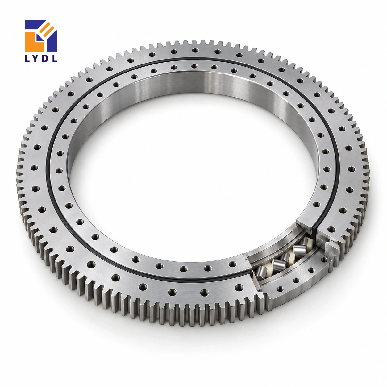
XA240685 is listed as an externally geared crossed roller reference with a 577 mm bore and 830.1 mm outside diameter. Its 68 mm height, module 8 gear and 102 teeth distinguish this package from the slimmer XA140640 listing.
XA240685: nominal LYDL listing. INA interchange unverified. Supplied execution requires an agreed drawing.
XA specification tables · Family technical reference
| Bore (mm) | Outside (mm) | Height H (mm) | Mass ≈ (kg) |
|---|---|---|---|
| 577 | 830.1 | 68 | 115 |
| Outer PCD La (mm) | Inner PCD Li (mm) | Outer holes na | Hole dB (mm) | Secondary h (mm) |
|---|---|---|---|---|
| 753 | 617 | 24 | 22 | 61 |
| Pitch d0 (mm) | Module m (mm) | Teeth z | Width b (mm) |
|---|---|---|---|
| 816 | 8 | 102 | 61 |
The 816 mm pitch diameter and 61 mm gear-width entry provide layout information for the perimeter drive. They do not specify allowable emergency-stop torque or the support capacity of the mounting joint. Describe maximum moving inertia, braking time and payload position, then check tooth loading and bearing loading separately. Review any drive backlash requirement in the context of system positioning, including bracket flexibility and the control strategy.
The outer connection lists twenty-four positions on a 753 mm circle with 22 mm holes; the inner fixing circle is 617 mm. Allow for the actual screw heads and tightening tools in the guard layout.
An eccentric fixture produces different combinations of gravity, inertia and process forces as the platform moves. Mark the approved fixture orientations and describe the maximum payload position in each. State whether a holding brake, motor control or separate machine device restrains the platform during dwell. Do not infer a holding function from the bearing or external gear listing.
For braking, provide the actual deceleration requirement, including any emergency event that differs from the programmed motion. Supply the complete moving inertia or enough mass-and-radius information for a review. Connect the resulting transmission request to the proposed pinion and its support structure. Check alignment over the gear face and show how mesh adjustment is secured.
The nominal 61 mm width does not define tooth quality, acceptable backlash or permissible contact stress. Those need a specific execution and engineering assessment. The supporting flange should be drawn with its real pockets and ribs, including the region that carries the drive bracket. Confirm tool access to the twenty-four outer fixing positions with the guard installed or removed according to the intended maintenance sequence.
Provide the complete inner connection from the offered drawing before manufacturing the top plate. Define acceptance at a useful equipment location, such as a fixture datum under a stated force, and distinguish that from component receiving checks. This creates a measurable selection objective without claiming a positioning result from tooth count. Transport and installation should also use the actual assembled mass and an approved support method, protecting exposed external teeth throughout handling.
The XA240685 gear row describes external teeth with module 8 and 102 teeth. Their product is 816 mm, matching the listed nominal pitch diameter. That arithmetic checks the relationship between three entries; it does not calculate a permissible tooth force. The physical outside diameter is 830.1 mm and the bore is 577 mm, so neither should be replaced by the pitch-circle value in a clearance drawing. Overall height H is 68 mm. Locate the gear face and the two mounting planes from the offered section before positioning a pinion. The tooth form, engagement, quality requirement and supplied material execution remain separate specification items. Keeping these definitions distinct prevents a correct transmission number from being used as the wrong housing dimension.
XA140640 has a 571 mm bore, close to the 577 mm listed here, but the rest of the layouts differ. The present outside envelope is 830.1 mm and overall H is 68 mm, compared with 742.3 mm and 50 mm for that other reference. A central opening that appears nearly unchanged can therefore conceal a substantial redesign at the perimeter and working stack.
Compare both sections with the real machine constraints. Include the external pinion, guard and motor-removal path. A bore-led shortlist is a useful start, but it should not determine a replacement or adapter before the full ring, connection and transmission geometry has been examined.
The listed external gear has 102 teeth and an 816 mm pitch circle. Its module 8 differs from the module 6 of XA140640. Identify a suitable proposed mating pinion and show the support arrangement rather than assuming the existing drive can remain. Confirm tooth execution and engagement through the actual offered configuration.
Record the motion cycle and process holding cases separately. Include moving mass distribution, eccentric tooling and relevant stopping conditions. A larger gear reference alone does not establish permissible torque. The listed 61 mm face width is geometric information; the required transmission performance needs assessment against the real pinion, material execution, support and duty.
The approximate listed mass makes the receiving and installation route worth planning before delivery. Check access to the seating and request handling guidance suitable for the supplied ring. Do not use an unapproved tooth, hole or seal feature as a lifting point. Protect machined surfaces from loose hardware and uneven temporary support.
The 753 mm outer and 617 mm inner fixing circles list twenty-four positions per ring. Add screw details, locating features and supporting sections to the assembly drawing. Review access to those connections with the drive in place. Inspect the prepared seating in a defined condition and use the agreed installation method rather than relying on tightening to force a distorted flange into conformity.
Provide the payload layout, operating schedule and required observation at the tool with the model enquiry. This extended XA designation is supported here by LYDL's nominal row; full original-brand interchange has not been independently established. Resolve the offered drawing and any constrained interfaces before purchase.
Agree the receiving checks and the separate installed test. Keep the actual drive settings and load configuration with the commissioning record. Discuss storage, contamination and service access as part of the supply enquiry. The shared workshop and application images communicate general arrangements and cannot certify testing or suitability of this individual component in the proposed fixture.
XA260560 is another substantial external-drive option at 456 × 708 × 68 mm. It shares the listed 68 mm height with this 577 × 830.1 × 68 mm row but uses module 10 and 69 teeth, compared with module 8 and 102 here. A common total height therefore does not preserve opening, support footprint or transmission.
If the central equipment forces the larger bore, show that equipment and its service route on the chosen layout. Check the base width and handling path as well as the motor position. Retain the actual load and motion cases in the enquiry. Size and approximate component mass can inform packaging decisions, while the offered execution and complete duty determine the technical assessment.
A handling platform with a substantial eccentric fixture is a representative design case. Assess loading, travel and stopping conditions, including the moment from the fixture above the ring plane.

Agree the gear-contact, dimensional and functional checks for the supplied drawing. Plan a stable shipping support that keeps lifting straps clear of exposed teeth.

The current LYDL row gives module 8, 102 teeth, an 816 mm pitch diameter and 61 mm gear width.
The reference lists 68 mm. The 61 mm secondary height and gear-width entries do not replace that total envelope.
Twenty-four positions on a 753 mm circle are listed with 22 mm holes. The inner circle is 617 mm, pending full drawing details.
No. Gear quality, backlash, structure, control and the complete bearing execution influence system positioning. Specify the required result and test condition.
None is established for this extended row. The LYDL drawing, quotation and agreed application review define the supply proposal.
Pinion inside: XI series. Standard external-gear group: XSA range.
For XA240685, provide braking data, fixture inertia and the pinion assembly section.