

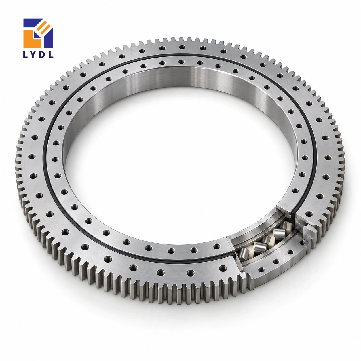
The XA240574 externally geared bearing is listed by LYDL at 480 × 695 × 77 mm. Its module 5 gear has 137 teeth; the separate 42 mm h and gear-width entries should not be mistaken for the overall height.
XA240574: nominal LYDL listing. INA interchange unverified. Supplied execution requires an agreed drawing.
XA specification tables · Family technical reference
| Bore (mm) | Outside (mm) | Height H (mm) | Mass ≈ (kg) |
|---|---|---|---|
| 480 | 695 | 77 | 84 |
| Outer PCD La (mm) | Inner PCD Li (mm) | Outer holes na | Hole dB (mm) | Secondary h (mm) |
|---|---|---|---|---|
| 640 | 508 | 18 | 18 | 42 |
| Pitch d0 (mm) | Module m (mm) | Teeth z | Width b (mm) |
|---|---|---|---|
| 685 | 5 | 137 | 42 |
An existing housing may appear compatible if a designer reads the 42 mm gear-width entry as bearing height. The current row explicitly lists H as 77 mm, so reserve that full reference envelope until the offered drawing confirms the axial details. Check where the pinion face sits relative to the two mounting planes. This model’s combination of height and gear dimensions deserves a section-based review rather than extrapolation from nearby XA references.
The listed outer fixing pattern has eighteen positions on a 640 mm circle with 18 mm holes; the inner circle is 508 mm. Verify angular positions and all inner fastening details before using a reused flange.
Name each axial face on the proposed assembly drawing and state which one sets the platform working height. Show the bearing overall envelope around those datums, then locate the gear face independently. This prevents the 42 mm secondary entry from becoming an unintended substitute for the 77 mm total-height reference. Check whether fasteners, covers or reliefs occupy the space beside the stepped regions.
If existing equipment was measured rather than drawn, record the measuring points and the assembled condition. A measurement across two accessible surfaces may not represent overall bearing height. Compare the resulting section with the LYDL proposal before manufacturing replacement plates. Review the eighteen-position outer connection as its own pattern, including angular alignment and local support.
A plate from a nearby model may contain incompatible holes even when its central opening appears usable. For an elevated fixture, give process-force locations relative to the actual ring plane after adapters and spacers are included. The difference between that plane and the working surface can matter to moment loading. Complete the identity and interface review before attributing any original-brand equivalence to this extended model.
The accepted supply drawing should resolve the axial package explicitly and provide one consistent basis for inspection.
The XA240574 gear row describes external teeth with module 5 and 137 teeth. Their product is 685 mm, matching the listed nominal pitch diameter. That arithmetic checks the relationship between three entries; it does not calculate a permissible tooth force. The physical outside diameter is 695 mm and the bore is 480 mm, so neither should be replaced by the pitch-circle value in a clearance drawing. Overall height H is 77 mm. Locate the gear face and the two mounting planes from the offered section before positioning a pinion. The tooth form, engagement, quality requirement and supplied material execution remain separate specification items. Keeping these definitions distinct prevents a correct transmission number from being used as the wrong housing dimension.
Preserve all three entries in this LYDL row: overall H is 77 mm, while h and gear width b are each 42 mm. They describe different features. Do not reduce total height to the smaller figure or expand the tooth face to match the overall stack. Ask for the offered section and locate the actual mounting planes and tooth position.
This distinction matters when a pinion bracket is retained from an existing machine. A bracket can appear compatible in plan and still put the pinion at the wrong axial level. Include the mating plate thickness, adapter and screw seats in the same drawing. Release manufacturing only against the resolved interface, with the original labels retained in the technical record.
The module 5 external gear lists 137 teeth and a 685 mm nominal pitch diameter. The row's 695 mm outside envelope is a separate clearance dimension. Identify the pinion and reduction proposed for the machine, including their support and adjustment. A relatively high tooth count does not establish positioning accuracy or remove the need to evaluate the actual mesh.
Describe the required movement and approach direction. If the platform reverses under an offset load, show that condition and the output point being observed. Ask for the offered tooth execution and any agreed inspection method. The product table provides nominal geometry and cannot supply an unsupported transmission force, backlash value or material specification.
The bore is 480 mm, and the attachment circles are 640 mm outside and 508 mm inside. Each ring lists eighteen positions. Show the actual screws, engagement and locating features on the mating parts. A broad platform may leave a long circumferential span between attachment locations, so review the real flange section and backing rather than assuming uniform support from a plan view.
Include pockets, access windows and connections to the machine frame. Check tool access around the external drive enclosure. Describe the geometry-check condition and assembly sequence for the offered execution. The count and hole diameter alone do not define an adequate joint or an approved payload for the proposed equipment.
LYDL's nominal website data supplies this page; a complete independent original-brand match remains unverified. Send the existing assembly section and explain which heights and pinion features are fixed. Resolve the offered configuration before treating the reference as an interchangeable replacement.
Define any receiving inspection by characteristic and method, then specify the separate installed test at the workpiece. Record the support, drive and loading state used for that test. Discuss protection of the tooth perimeter and machined seating during shipment and storage. These details make the request specific to XA240574 without converting the shared inspection illustration into evidence of a model-specific test.
XA140540 has a 471 mm bore, close to the 480 mm listed here, yet its H is 48 mm rather than 77 mm. Its module 6, 105-tooth transmission differs from this module 5, 137-tooth row. Another nearby candidate, XA160596, provides 510 × 712.3 × 55 mm with module 6 and 117 teeth.
Use these differences to test the equipment constraints, particularly the unusually separate total-height and tooth-face entries of XA240574. Draw the retained pinion and the actual platform datum before proposing an adapter. A close opening does not preserve stack, attachment or gear execution. Each extended reference needs its own offered drawing and review of the operating cases.
Keep the resolved tooth-face location visible on the released section.
A rotary fixture with stepped upper and lower mounting planes is an illustrative study. Assess tool clearance throughout the axial stack and include the moment introduced by the elevated workpiece.

Tie axial measurements to the accepted drawing revision and name each measured face. Pack the stepped assembly so external restraints do not act through an unsupported shoulder.

No. The current LYDL table lists H = 77 mm. Its h and gear-width entries are separately listed as 42 mm.
The reference gives 137 teeth at module 5 and a 685 mm pitch diameter.
No. XA240574 lists eighteen outer positions; XA260560 lists twenty-eight. Compare the full patterns rather than the model sequence.
Use an accepted section drawing identifying each mounting face and gear location. The website row is reference data for that review.
No exact standard match was established for this extended LYDL model. Avoid treating an N suffix as proof of interchange.
Pinion inside: XI series. Standard external-gear group: XSA range.
For XA240574, attach a section that clearly labels H, h, gear width and both mounting planes.