

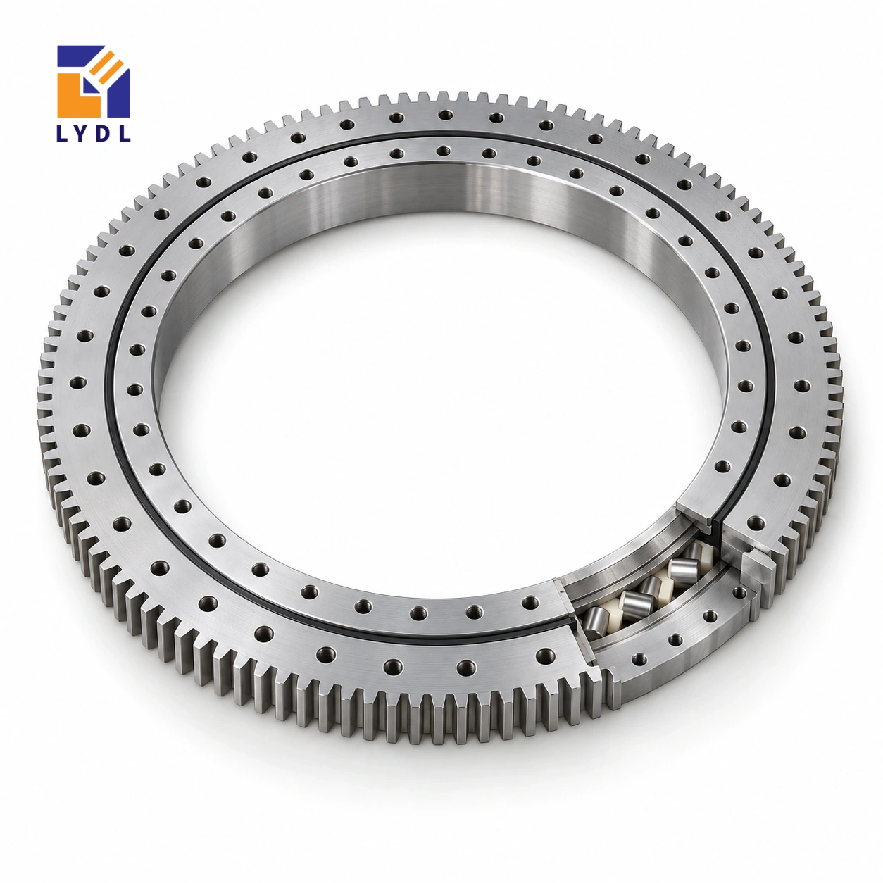
XA180309 is a LYDL-listed external gear cross roller reference measuring 235 × 408.4 × 60 mm. Its module 5, 80-tooth gear and 52.5 mm gear-width entry should be reviewed with the bearing support rather than treated as a complete drive specification.
XA180309: nominal LYDL listing. INA interchange unverified. Supplied execution requires an agreed drawing.
XA specification tables · Family technical reference
| Bore (mm) | Outside (mm) | Height H (mm) | Mass ≈ (kg) |
|---|---|---|---|
| 235 | 408.4 | 60 | 30 |
| Outer PCD La (mm) | Inner PCD Li (mm) | Outer holes na | Hole dB (mm) | Secondary h (mm) |
|---|---|---|---|---|
| 359 | 259 | 24 | 13 | 52.5 |
| Pitch d0 (mm) | Module m (mm) | Teeth z | Width b (mm) |
|---|---|---|---|
| 400 | 5 | 80 | 52.5 |
The listed 60 mm overall height is larger than the 52.5 mm gear width and secondary height. A guard or pinion bracket designed around only the tooth face can therefore interfere with a ring shoulder or mounting plate. Work from a section showing all mating faces, fastener projections and the pinion engagement zone. This is an extended LYDL listing; its N-labelled row is not presented as an independently verified standard INA match.
The outer connection lists twenty-four positions on a 359 mm circle and 13 mm holes; the inner circle is 259 mm. Obtain its complete hole pattern and shoulder details before machining either plate.
Start with a section of the ring and mark the two mounting planes, the gear face and the pinion support. Identify whether the pinion remains fixed axially while the surrounding machine flexes under load. The reference gear width does not prove acceptable contact under every loaded condition. Ask for an assessment using the actual bracket, tooth requirements and duty.
Describe how adjustment is locked after the mesh is set and how it can be checked during maintenance. On a handling swivel, draw the payload in its highest and furthest allowed positions. A load that moves towards the axis during travel can change both inertia and moment direction. Provide the approved sequence rather than a maximum weight with no location.
Review where the motor and guard can be removed without lifting the rotating platform. Space that appears unused during operation may be required for dismantling a shaft or coupling. Before manufacturing an adapter, check that its thickness leaves the working height and gear alignment within the machine design. Retain the website row as a reference for enquiry, then base the final interfaces on a consistent accepted drawing revision.
This extended listing should not be used to combine dimensions borrowed from another original-brand item.
The XA180309 gear row describes external teeth with module 5 and 80 teeth. Their product is 400 mm, matching the listed nominal pitch diameter. That arithmetic checks the relationship between three entries; it does not calculate a permissible tooth force. The physical outside diameter is 408.4 mm and the bore is 235 mm, so neither should be replaced by the pitch-circle value in a clearance drawing. Overall height H is 60 mm. Locate the gear face and the two mounting planes from the offered section before positioning a pinion. The tooth form, engagement, quality requirement and supplied material execution remain separate specification items. Keeping these definitions distinct prevents a correct transmission number from being used as the wrong housing dimension.
The 235 mm bore, 408.4 mm outside envelope and 60 mm overall height make three distinct layout constraints. Draw the machine's working plane relative to the bearing seating. Include the fixture plate and any adapter between them. A suitable opening can still leave the work surface too high, or place the external pinion at an inconvenient level.
If the station replaces an existing support, identify which heights are fixed by neighbouring equipment. A compensating plate changes more than the final level: it can alter tool access, connection engagement and the height at which forces enter the structure. Submit the complete stack rather than asking for approval based on the bare bearing dimensions alone.
This reference lists module 5 and eighty teeth, with a 400 mm nominal pitch circle. Place the pinion beside the loading mechanism and show both through their operating movements. Check interference when the loader approaches with a part and when maintenance equipment reaches the motor. The protective enclosure occupies additional space around the mesh.
Describe acceleration and dwell separately. If a clamp or stop acts while the table is stationary, show its reaction path. An external gear provides a place to transmit motion, but it does not define the machine's holding arrangement or approved emergency-stop condition. Ask for review using the proposed pinion, motor support and actual duty instead of assigning performance from the module entry.
An elevated fixture can create an overturning moment from forces applied above the ring. Give the force directions and heights for normal loading, processing and unloading. Include the moving tooling mass and any offset part. The approximate 30 kg bearing mass is useful for handling the component and must not be read as a permissible payload.
There are twenty-four listed fixing positions at each connection, with 359 mm and 259 mm circles. The drawing should show the offered screw details and the material behind the full annuli. Review local cutouts and the junction between any welded frame and machined seating. Establish a geometry-check condition representative of assembly. Avoid relying on bolt tightening to correct a poor seating or an uncertain pilot fit.
This extended XA designation is documented here from LYDL's nominal website row. A complete independent original-brand correspondence has not been established. Request the offered section and connection drawing, then compare every constrained feature before releasing an adapter or accepting a replacement proposal.
State whether the unit faces dust, washdown spray or long idle periods, and ask how the proposed seals and service points suit that environment. Keep the confirmed drive data with the bearing revision. For acceptance, distinguish agreed component inspection from a loaded test at the machine's working plane. That record gives later spare orders and fault investigations a defined configuration to reference.
XA160407 increases the bore from 235 to 335 mm and outside diameter from 408.4 to 503.3 mm, but lowers nominal H from 60 to 50 mm. The gear module remains 5 while the tooth count changes from eighty to ninety-nine. A larger opening can therefore come with a lower ring stack and a different ratio.
Put the loader and workpiece on both sections before changing a base drawing. Check whether the revised pinion level, pattern and maintenance path remain practical. The twenty-four-position connection here differs from the thirty-position XA160407 pattern. A candidate comparison should identify the actual constraint being solved, then lead to an individual LYDL drawing enquiry with the intended process and motion attached.
A material-handling swivel with an external motor is an illustrative study. Describe lifting and lateral acceleration at the payload centre, including its offset above the bearing plane.

Set the required gear-face and mounting-face checks in the inspection plan. Shipping protection should cover the outside tooth perimeter without trapping hard debris against it.

LYDL lists 60 mm overall height. The 52.5 mm h and gear-width entries describe separate features.
Module 5, 80 teeth and a 400 mm pitch diameter are listed. Tooth quality, backlash and permitted forces require confirmation.
The table lists twenty-four positions on a 359 mm circle, with 13 mm hole diameter. The inner fixing circle is 259 mm.
No exact standard original-brand row was established for this extended model. Review the LYDL drawing and the actual machine requirements.
Its distance above the bearing plane changes the overturning effects of lateral forces. A mass figure alone misses that geometry.
Pinion inside: XI series. Standard external-gear group: XSA range.
For XA180309, include a section through the pinion engagement and the full axial installation stack.