

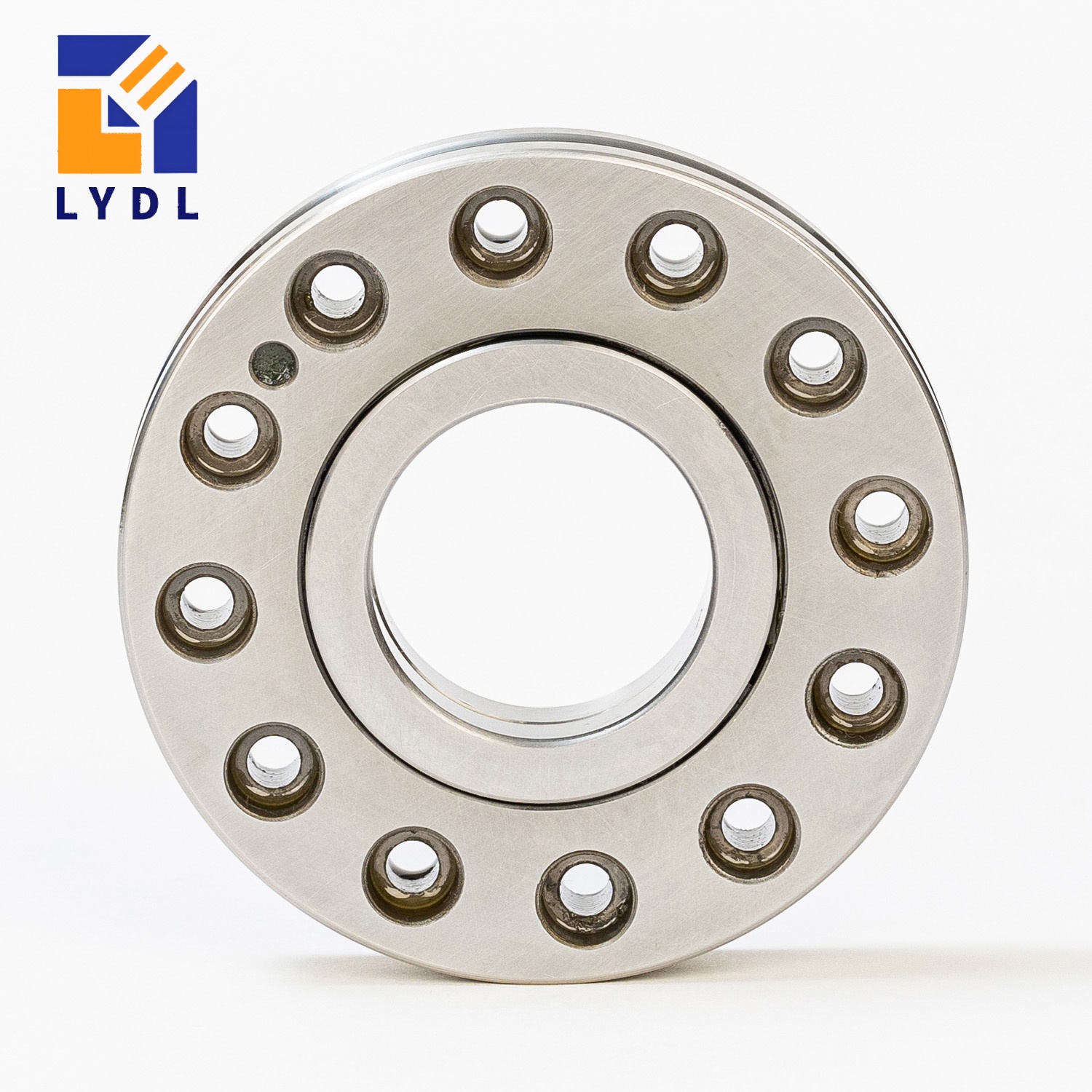
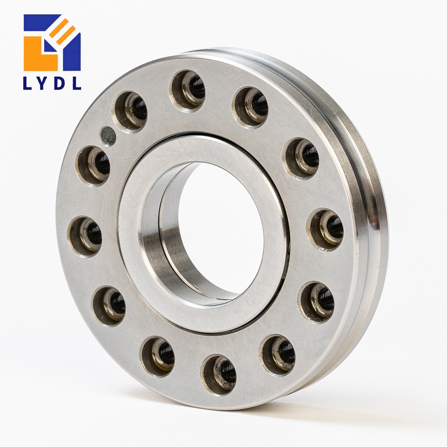
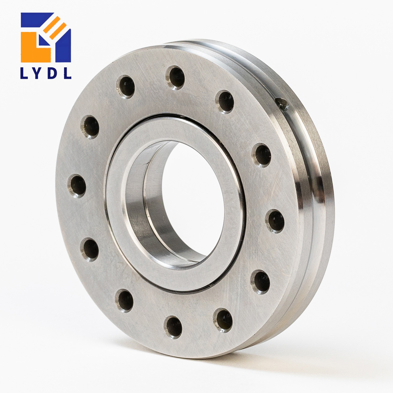
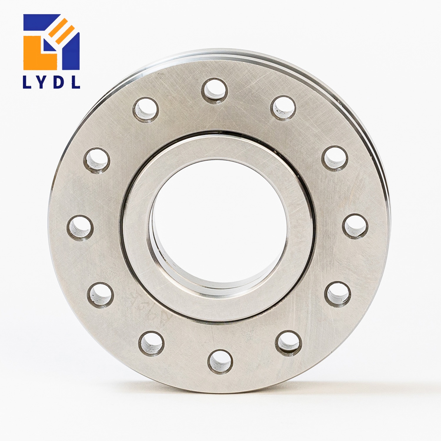
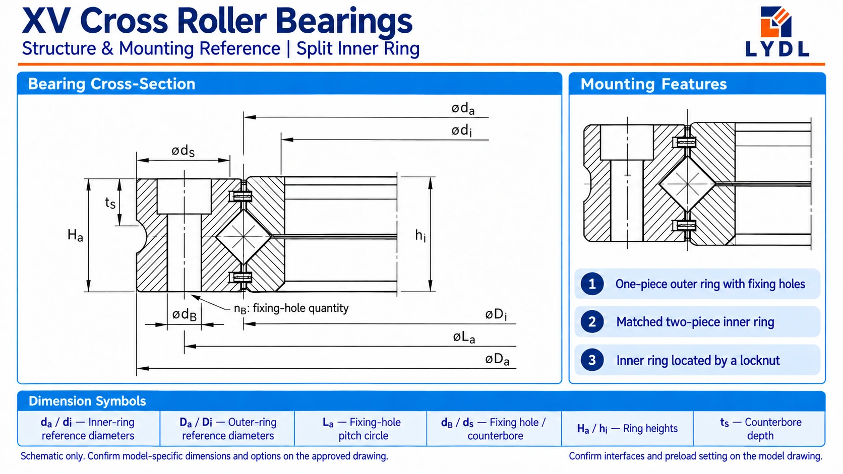
XV cross roller bearings are a compact crossed roller reference family covering nine listed sizes from XV30 to XV110. The reference arrangement screws the outer ring to the adjacent construction and locates the split inner ring with a locknut. That axial locating arrangement allows the clearance or preload setting to be adjusted. Selecting an XV bearing therefore includes the shaft thread and locknut installation, as well as its nominal bore and outside diameter.
The crossed roller layout can carry radial force, axial force in both directions and a tilting moment within one bearing position, subject to the selected design and load review. It does not eliminate the need to check the shaft, fixing screws or support plate. The official Schaeffler KSX reference explains the XV mounting concept; supplied LYDL specifications are defined by the agreed drawing.
All dimensions below use mm and mass uses kg. The source distinguishes outer-ring height Ha from inner-ring height hi. Across these rows, hi is 1 mm greater than Ha. Keep both dimensions in the assembly stack rather than replacing them with one generic bearing width. Approximate mass helps an initial moving-axis assessment but does not define a permissible payload.
| Model | di (mm) | Da (mm) | Ha (mm) | hi (mm) | Mass (kg) | Drawing |
|---|---|---|---|---|---|---|
| XV30 | 30 | 75 | 14 | 15 | 0.37 | Drawing |
| XV40 | 40 | 85 | 14 | 15 | 0.44 | Drawing |
| XV50 | 50 | 100 | 16 | 17 | 0.67 | Drawing |
| XV60 | 60 | 110 | 16 | 17 | 0.75 | Drawing |
| XV70 | 70 | 120 | 16 | 17 | 0.84 | Drawing |
| XV80 | 80 | 135 | 18 | 19 | 1.18 | Drawing |
| XV90 | 90 | 145 | 18 | 19 | 1.29 | Drawing |
| XV100 | 100 | 170 | 22 | 23 | 2.31 | Drawing |
| XV110 | 110 | 180 | 22 | 23 | 2.48 | Drawing |
La is the outer-ring fixing pitch circle in the source drawing. nB counts the fixing holes; dB, ds and ts retain the drawing’s hole and counterbore symbols. Di and da are separate interface diameters. Their capitalisation matters. Confirm the surfaces indicated by each symbol before adding a counterbore or shoulder to the mating component.
| Model | Di | da | La | nB | dB | ds | ts | Drawing |
|---|---|---|---|---|---|---|---|---|
| XV30 | 42.5 | 41.5 | 60 | 12 | 4.6 | 8 | 4.6 | Drawing |
| XV40 | 52.5 | 51.5 | 70 | 12 | 4.6 | 8 | 4.6 | Drawing |
| XV50 | 64.5 | 63.5 | 85 | 12 | 5.6 | 10 | 5.4 | Drawing |
| XV60 | 74.5 | 73.5 | 95 | 16 | 5.6 | 10 | 5.4 | Drawing |
| XV70 | 84.5 | 83.5 | 105 | 16 | 5.6 | 10 | 5.4 | Drawing |
| XV80 | 95.5 | 94.5 | 120 | 16 | 6.6 | 11 | 6.4 | Drawing |
| XV90 | 105.5 | 104.5 | 130 | 16 | 6.6 | 11 | 6.4 | Drawing |
| XV100 | 117.5 | 116.5 | 150 | 16 | 9 | 15 | 8.5 | Drawing |
| XV110 | 127.5 | 126.5 | 160 | 16 | 9 | 15 | 8.5 | Drawing |
The hole count increases from 12 on XV30–XV50 to 16 on XV60–XV110. Hole diameters and head recesses also change across the range. A larger XV model consequently needs a new fastening review, even if the designer can enlarge the shaft opening without difficulty. Leave practical access to the screws and the locknut after guards, sensors and couplings have been installed.
The locknut is a locating and adjustment component within the reference arrangement. Its contact face, shaft-thread geometry and locking method affect the assembled condition. Follow the approved assembly procedure when setting the bearing, and evaluate movement after the surrounding fasteners have been tightened. Avoid treating an arbitrary locknut torque as a universal preload instruction for all nine sizes.
Define what is to be measured during acceptance: axial movement, radial movement, breakaway torque, running torque or rotational runout. A result without the load, temperature and measurement position is difficult to compare. When a small motor or direct drive must move the axis smoothly, reserve enough torque margin for the agreed bearing setting and the remaining transmission losses.
Compare SX bearings with clamping-ring retention if the housing is already designed for a retained thin-section ring. If the machine benefits from bolted attachment at both bearing rings, review RU integrated-ring options. Neither alternative becomes an XV replacement merely because its bore is the same.
At 50 mm bore, XV50 has a 100 mm outside diameter and separate heights of 16 and 17 mm. At 60 mm bore, XV60 grows to 110 mm outside diameter while retaining those height values. At 100 mm bore, XV100 requires a 170 mm outside diameter with heights of 22 and 23 mm. These examples show why envelope checks should use the actual row rather than a constant wall-thickness assumption.
XV80 and XV90 offer another useful comparison: their outside diameters are 135 and 145 mm, and both retain outer and inner heights of 18 and 19 mm. Both list sixteen fixing holes, but that shared count does not mean the mounting circles coincide. The La values are 120 and 130 mm. Retain the selected circle in the base drawing and check its relationship to the surrounding walls. A correct screw count on the wrong pitch circle still prevents assembly.
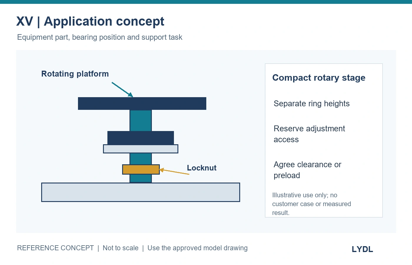
Reserve adjustment and inspection access in the assembled equipment. A locknut that can be reached on a bare shaft may become inaccessible behind the motor, encoder or stage cover. Document which components must be installed before adjustment and which surfaces remain available for measurement. If the measured setting falls outside the agreed criterion, follow the specified adjustment procedure and recheck the result before fixing the final locking arrangement. That practical assembly sequence should be settled while the machine interfaces are still being designed.
Retain the adjustment method and inspection record for service, so a replacement can be installed to the same agreed operating condition.
A compact positioning stage can mount the XV outer ring to its base and carry a rotating platform on the inner-ring side. The shaft and locknut sit below or inside that platform according to the assembly design. The bearing supports the platform’s axial loading and any eccentric payload moment. The illustration presents this mechanical arrangement as a concept, with no claim of measured positioning accuracy.
Describe the equipment’s motion in terms that reveal the bearing duty: continuous rotation or limited travel, acceleration, dwell, reversal frequency and the heaviest offset load. Include any external clamping or process force applied while the axis is stationary. An unloaded positioning demonstration is not sufficient evidence that the same setting will meet torque and deflection requirements under the real task.
The published XV reference data distinguish basic axial and radial ratings and two speed conditions, one with preload and one with clearance. Use the applicable model data sheet when assessing those values. Review the reference catalogue’s conditions and the actual supplied configuration before specifying an operating limit. The dimension tables establish an installation shortlist; operating acceptance still needs a defined load case and assembled setting.
LYDL offers P5 as the baseline, with P4 or P2 specified where required. State the desired precision independently of the adjustment condition. Agree lubrication, sealing, load, measurement datums and installation acceptance with the selected model. Keep the final machine’s positioning target separate from the bearing’s tolerance class; drive control and structural compliance also contribute to the result.
Use the parent cross roller bearing range to compare other support architectures. For a bolted-ring reference in a different range, see XSU series bearings. To request an XV drawing and quotation, send the model, quantity, shaft-thread section, mounting interfaces and duty. Identify whether the enquiry concerns a new design or a replacement in an existing assembly.
The guide includes nine: XV30, XV40, XV50, XV60, XV70, XV80, XV90, XV100 and XV110. Each has a separate dimensional row and mounting row.
They describe different ring heights in the source drawing. The inner-ring value exceeds the outer-ring value by 1 mm in these nine records. Both are needed for the shaft and housing stack.
No universal torque is specified here. Use the selected drawing and assembly procedure, with a defined clearance or preload target and an agreed inspection method.
It represents a different operating condition. Review the applicable rating basis, lubrication and heat balance for the actual assembled setting rather than transferring that speed directly.
No external gear is defined by this XV guide. Its key reference features are the outer-ring fixing arrangement and adjustable split inner ring. Compare a geared series separately if a gear drive is required.