

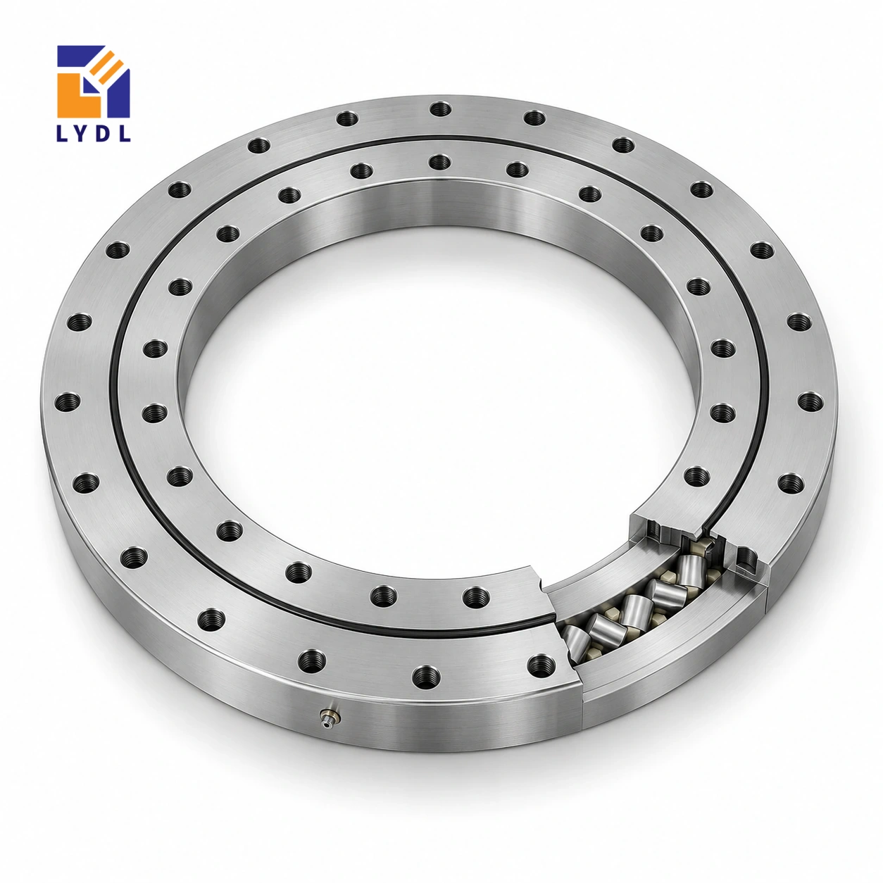
XU160405 is a gearless cross roller slewing bearing reference around a 336 mm centre opening. The 474 mm outside diameter, 46 mm height and thirty-hole connections provide the basic layout for a larger rotary support whose stiffness and operating cycle still require definition.
XU160405 original-reference geometry: Catalogue 404, pp. 90–93. LYDL supply follows its accepted drawing.
XU specification tables · Family technical reference
| Bore (mm) | Outside (mm) | Height H (mm) | Mass ≈ (kg) |
|---|---|---|---|
| 336 | 474 | 46 | 25 |
| Outer PCD La (mm) | Inner PCD Li (mm) | Outer holes na | Inner holes ni | Hole dB (mm) |
|---|---|---|---|---|
| 450 | 360 | 30 | 30 | 14 |
A broad fixture can have a modest total mass yet a large polar inertia when that mass is distributed near its edge. For an indexing platform, provide the mass distribution and acceleration instead of specifying only the total payload. Compare the XU roller arrangement with the same-envelope VU200405 ball reference where useful, but obtain the corresponding execution data before deciding on running resistance or angular deflection. Envelope equality does not predict servo response.
Thirty positions on 450 mm and 360 mm fixing circles require deliberate tool access. Locate dowels, guards and drive brackets after checking the screw sequence, and make the grease-service arrangement accessible in the finished machine.
List each station with its fixture mass, workpiece mass and distance from the axis. Then mark process forces separately from gravity. A balanced arrangement can become eccentric when one station is emptied for loading or maintenance. Decide which occupancy patterns the control system permits and which are excluded from operation.
This gives a clearer selection basis than multiplying the largest single workpiece by the number of stations, which would miss both inertia distribution and asymmetric conditions.
The XU160405 dimensions describe several different interfaces. Bore 336 mm and outside diameter 474 mm set the basic radial envelope; overall H = 46 mm sets the bearing’s axial reference. Fixing circles La = 450 mm and Li = 360 mm locate the outer and inner attachment patterns, rather than the free opening or roller diameter. The reference lists 30 fixing positions on each ring. A circle and a count do not fully describe a hole: seat details, thread engagement and angular orientation still belong on the accepted drawing. Approximate mass 25 kg is a component property, not an approved payload. Reading these fields separately helps prevent a correct catalogue number being transferred to the wrong feature of a mating plate.
Define the reason for considering XU160405 or VU200405 in the same machine layout. The shared basic envelope can simplify a dimensional study, but it does not settle running resistance, clearance or loaded response. List the existing interfaces that must stay and the equipment result that the selected arrangement must achieve.
Use a drawing overlay to compare pilots, attachment details and axial location. Then request the offered execution information relevant to the operating requirement. A ring with a different contact principle should not be treated as a correction for an undiagnosed flexible table or transmission concern. If the machine already operates, record the observed behaviour at a named output point with the load and approach direction stated. These observations help focus the proposal. They also make it possible to judge whether retained plates and brackets remain appropriate, rather than using the matching nominal dimensions as the entire replacement justification.
Create a station schedule with each fixture, product and attached device listed at its actual radius. The full moving mass matters, but so does its distribution around the axis. A table carrying empty fixtures has inertia even before a workpiece is loaded. Identify the combinations of occupied stations permitted by the machine sequence.
Describe acceleration, deceleration, dwell and any reverse movement. Keep process forces during the stopped phase separate from the motion description. If loading or unloading occurs while another station remains occupied, show the resulting asymmetric state. Identify which workpiece configurations and tool extensions are approved. This gives the drive and support review a defined operating envelope without deriving a permissible torque or moment from the bearing dimensions. It also provides a useful change-control record: a new nest at a larger radius can alter both inertia and eccentric loading even if its nominal payload is unchanged.
Show the 450 mm and 360 mm fixing circles beside the actual screw tools and surrounding equipment. Check access to each connection after the central services, drive and tooling are fitted. A maintenance path should include removal of a fastener and withdrawal of the affected part, not merely contact with the screw head.
Review support contact beneath the attachment regions and include real pockets, ribs and bracket connections on the structural drawing. The separate drive can introduce a concentrated reaction near the ring. Its location belongs in the same assessment as the platform loads. Confirm the offered hole and shoulder details before machining either plate. A fabricated base should be inspected in its final prepared condition, with the relevant support arrangement recorded when it influences the result. This allows the ring to be attached to a defined surface rather than used to correct uncertain geometry during tightening.
Receiving inspection should identify the supplied model and the agreed dimensional features. An installed test should state the tooling set, station loading, motion and measurement location. Keep these records distinct, since a free-ring observation cannot establish the performance of the complete carousel under process forces.
During assembly, note any change in rotation behaviour as plates, fixtures and the drive are added. Investigate an unexpected change before compensating with motor settings. At commissioning, record a repeatable reference configuration that can be reproduced after maintenance. Retain the bearing drawing, adapter revisions and the station schedule with that baseline. When ordering a spare, provide the actual accepted configuration rather than only a historic model number. The proposed LYDL execution, inspection scope and shipment protection can then be defined for the task. This supports a technical supply discussion without assigning undocumented precision, life or capacity claims to the catalogue envelope.
For an initial dimensional shortlist, place XU160405 (336 × 474 × 46 mm) beside XU080264 (215.9 × 311 × 25.4 mm) and XU160260 (191 × 329 × 46 mm). These nearby requested references provide a useful envelope comparison, not a sequence of increasing approved load ratings. Compare their actual bolt circles and support faces before deciding which deserves a detailed drawing review. A smaller bore can conflict with the service route, while a different outside diameter changes the available backing annulus. Retain the complete model in every enquiry so a proposal is tied to the intended row. Only the accepted execution and application assessment can resolve the final choice.
A multi-station assembly table is a representative scenario. Include the most uneven combination of occupied stations and examine process forces that act while the table is stopped.

Define a mounted functional check as part of the commissioning plan. Discuss transport support for the ring so lifting and securing do not load a thin local section.

The catalogue reference is 336 mm bore, 474 mm outside diameter and 46 mm height, with an approximate mass of 25 kg.
Their basic envelopes match, but the roller and ball arrangements differ. Confirm ratings, running requirements, locating features and supplied execution before replacement.
Thirty per ring are listed on the 450 mm outer and 360 mm inner fixing circles. Check every associated screw detail.
It affects the rotating inertia and can increase overturning effects. Total mass by itself does not define the drive and support loads.
The most unbalanced station loading or the largest process force may govern. Describe these alongside the moving and braking cases.
Roller interface comparison: XSU series. Ball-contact option: VU range.
Supply station masses, radii and dwell-process forces when asking LYDL to review XU160405.