

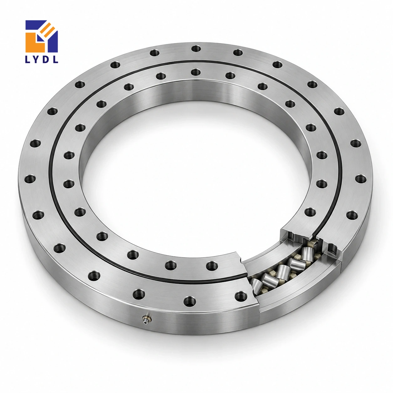
XU120222 is an ungeared cross roller slewing bearing reference with a 140 mm bore, 300 mm outside diameter and 36 mm height. Its broad radial envelope should be evaluated as a complete support layout rather than inferred from the number 222 in the model.
XU120222 original-reference geometry: Catalogue 404, pp. 90–93. LYDL supply follows its accepted drawing.
XU specification tables · Family technical reference
| Bore (mm) | Outside (mm) | Height H (mm) | Mass ≈ (kg) |
|---|---|---|---|
| 140 | 300 | 36 | 12 |
| Outer PCD La (mm) | Inner PCD Li (mm) | Outer holes na | Inner holes ni | Hole dB (mm) |
|---|---|---|---|---|
| 270 | 170 | 12 | 12 | 18 |
A fixture plate may fit the outside diameter while leaving the bearing incompletely backed beneath its mounting region. Sketch the actual contact annuli and locate the 270 mm and 170 mm fixing circles on that section. Review flange bending, screw load distribution and the distance from the workpiece force to the support plane. Adding a heavy top plate changes both the stiffness and the moving inertia, so include it in the duty description.
Twelve holes per ring and an 18 mm reference hole diameter are listed. Confirm screw-head accommodation and wrench clearance early, especially if the assembly is approached from only one side.
The heaviest payload position may differ from the position with the longest lever arm. Plot both on the station layout and identify where the drive accelerates while the gripper is extended. If several nests share the table, show the permitted combinations of occupied and empty stations. This exposes unbalanced conditions that an average payload misses.
Keep the final selection tied to approved operating cases; changing nest reach later is a machine change even when the workpiece weight stays constant.
The XU120222 dimensions describe several different interfaces. Bore 140 mm and outside diameter 300 mm set the basic radial envelope; overall H = 36 mm sets the bearing's axial reference. Fixing circles La = 270 mm and Li = 170 mm locate the outer and inner attachment patterns, rather than the free opening or roller diameter. The reference lists 12 fixing positions on each ring. A circle and a count do not fully describe a hole: seat details, thread engagement and angular orientation still belong on the accepted drawing. Approximate mass 12 kg is a component property, not an approved payload. Reading these fields separately helps prevent a correct catalogue number being transferred to the wrong feature of a mating plate.
Put the bearing footprint over a section of the proposed base rather than checking it only in plan view. The 300 mm outside envelope can fit inside a housing while the region beneath the connection remains interrupted by pockets, ribs or access openings. Identify the actual contact annuli and the route by which each side of the assembly transfers forces into the machine frame.
The 140 mm bore is useful for an initial space study, but the central equipment also needs its mounting features and installation route. Check the inner screw tools beside that equipment. A plate whose centre is stiff can still bend locally at the bearing connection. Show those local sections, not just the maximum plate thickness. If the base is fabricated, keep its final machining and inspection condition on the record. This gives the reference dimensions a practical meaning and allows the bearing proposal to be evaluated with the support that will actually be manufactured.
List the nests and grippers around the table with their mass and radial position. Separate fixed tooling from products that enter and leave during the cycle. Identify which occupied and empty combinations are allowed by the controls. A fully loaded carousel may be more balanced than a partially loaded one, so an average payload does not describe every relevant condition.
Show the gripper reach at pickup, transfer and release. Include forces from product contact or a stationary tool during dwell, with their heights above the ring plane. If the table accelerates before the gripper retracts, describe that state explicitly. State the normal stop and any separate emergency deceleration condition. These details allow gravity, process forces and inertia to be reviewed on their own terms. They also provide a reference for later tooling changes: increasing reach or changing station occupancy can alter the equipment duty even when the maximum workpiece mass remains unchanged.
Place both fixing circles on the assembly drawing with the complete hole and screw-seat information from the offered execution. The 18 mm reference hole diameter should not be used to invent a screw-head recess or engagement depth. Identify which plate provides each threaded connection and how concentric location is established.
Check the sequence for installing the ring, platform, drive and central services. Include the size of the tightening tools and the clearance to remove a screw, not only access to its head. If covers must be removed for inspection, show their supported maintenance position. The separate drive can introduce forces at a bracket that lies close to the bearing flange; include that attachment in the structural layout. A well-defined connection permits assembly without using the ring to force an uncertain pilot or distorted plate into position. Keep any approved adapter and its drawing revision with the bearing order record.
State the result the completed carousel must achieve at a named working datum. That may involve station presentation under a process force, repeatable movement between positions or acceptable behaviour during reversal. Describe the tooling configuration and operating state used to judge it. A component receiving check and an installed machine test should remain separate records.
Provide the operating sequence, mating drawing and actual environmental conditions with the model request. Ask for the offered LYDL execution and the data applicable to those conditions. No precision class, preload or permissible speed should be inferred from this page's geometry. At delivery, preserve identification and protect the mounting faces from loose fixture hardware. Record the initial assembly observations before adjusting the transmission to compensate for unexpected resistance. These steps support a traceable proposal and make later troubleshooting more effective than relying on the catalogue number alone. They also clarify what remains an equipment responsibility and what belongs to component supply.
For an initial dimensional shortlist, place XU120222 (140 × 300 × 36 mm) beside XU120179 (124.5 × 234 × 35 mm) and XU080149 (101.6 × 196.85 × 22.22 mm). These nearby requested references provide a useful envelope comparison, not a sequence of increasing approved load ratings. Compare their actual bolt circles and support faces before deciding which deserves a detailed drawing review. A smaller bore can conflict with the service route, while a different outside diameter changes the available backing annulus. Retain the complete model in every enquiry so a proposal is tied to the intended row. Only the accepted execution and application assessment can resolve the final choice.
A material-transfer carousel with a radial gripper is one possible use study. Compare the empty return stroke with the loaded pickup position because the largest moment may occur away from the nominal station.

Agree the support condition for rotation measurements. Pack the ring flat on a suitable support, isolating machined faces from pallet fasteners and loose fittings.

No. The cited bore is 140 mm and the outside diameter is 300 mm; use the actual parameter table for layout work.
The reference uses 270 mm externally and 170 mm internally, with twelve fixing positions on each ring.
The support needs to transfer load without excessive local bending. Review the contact annuli and flange section rather than relying on outside diameter alone.
Motor selection also depends on the complete rotating inertia, friction, acceleration and external loads. The bearing mass is only one input.
Include pickup, transport and release conditions, with their load locations. The governing case may occur between the fixed stations.
Roller interface comparison: XSU series. Ball-contact option: VU range.
Provide the carousel plate section, maximum gripper reach and acceleration profile for an XU120222 enquiry.